
operation. The fourth indicator is a split-legend
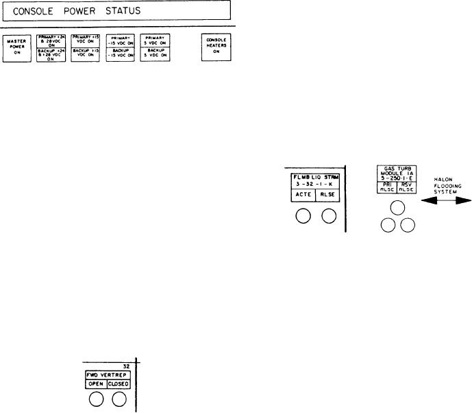
The second subsection contains the Halon
status indicator labeled PRIMARY 15 VDC
flooding system. Halon is the extinguishing agent
ON and BACKUP 15 VDC ON. The upper
used to combat fires in high risk areas. The Halon
portion of the indicator illuminates white to
system protects both GTM modules; all four
indicate the primary 15 volt dc power converter
SSDG enclosures; the engine room; all three
is in operation. The lower portion of the indicator
AMRs; the recovery, assist, securing, and
illuminates white to indicate the backup 15 volt
traversing (RAST) equipment room; the paint
dc power converter is in operation. The fifth
mixing room; and the flammable gas and
indicator is a split-legend status indicator labeled
liquid storerooms. The DCC has indicators,
PRIMARY 5 VDC ON and BACKUP 5 VDC
corresponding to the spaces, that display whenever
O N . The upper portion of the indicator
Halon has been released to one of these spaces.
illuminates white to indicate the primary +5 volt
Halon release and actuation is displayed on
dc power converter is in operation. The lower
the DCC with two types of indicator arrangements.
portion of the indicator illuminates white to
The first type is for spaces that have only primary
indicate the backup +5 volt dc power converter
Halon protection. It contains two indicators
is in operation. The sixth push-button indicator,
labeled ACTE and RLSE. The associated ACTE
labeled CONSOLE HEATERS ON, illuminates
indicator illuminates in response to a pressure
white to indicate the console heaters are energized.
switch contact closure that activates when the CO2
Heater power is applied when the console power
actuation system is operated. The RLSE indicator
circuit is de-energized.
illuminates to indicate Halon release in the
associated space. The second indicator arrange-
ment is for spaces that have primary and reserve
Halon protection. This arrangement contains
three indicators to display Halon actuation,
primary Halon release, and reserve Halon release.
The associated actuation indicator illuminates in
response to a pressure switch contact closure that
activates when the CO2 actuation system is
operated. The PRI RLSE indicator illuminates to
Miscellaneous Fire Fighting Section
indicate primary Halon release in the associated
space. The RSV RLSE indicator illuminates to
This section is the uppermost section of the top
panel. It is divided into two subsections, one con-
indicate reserve Halon release in the associated
space.
taining the AFFF sprinkling system valves and the
other containing the Halon flooding system. The
AFFF sprinkling system valves subsection shows
the status of the four AFFF sprinkling valves.
These valves control the sprinkling of AFFF at
the two vertical replenishment (VERTREP) sta-
tions, forward (FWD) and aft (AFT), and the
sprinkling systems in the two helicopter hangars.
These valves are activated locally and their open
or closed status is shown on the DCC.
Open and closed valve indication for sprinkler
Associated with the miscellaneous fire fighting
section is a horizontal grouping of alarm
control valves at the forward and aft VERTREP
indicators, labeled SUMMARY and INDEP. The
and helicopter hangars is provided on the DCC
first indicator is labeled CONSOLE HIGH TEMP
by two indicating lights. The OPEN indicator light
ALARM. This alarm indicator illuminates red to
illuminates green to indicate the sprinkler control
valve is open. The CLOSED indicator light
indicate the console temperature has exceeded the
preset limit. The second alarm indicator, labeled
illuminates white to indicate the valve is closed.
AFFF SPRKLNG ACTUATION ALARM,
illuminates red when any one of the AFFF
sprinkling system alarms occur. The third
indicator, labeled MISSILE CO2 FLOOD INNER
RING ALARM, illuminates red to indicate CO2
flooding for the inner ring of the missile launcher.
9-44