T h e potable water system stores and
for potable water pump No. 1 is functionally
distributes brominated water required by the
identical.
ship's crew and equipment. There are four potable
water tanks. The system is served by two
centrifugal pumps. Either pump can take suction
from any of the four tanks. The pump discharges
to either the filling and transfer main or to the
service main. The system is designed for local
start-up and unattended operation. All the system
components being monitored or controlled are
located in AMR No. 3.
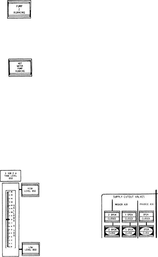
The second indicator, labeled HOT WATER
PUMP RUNNING, illuminates green to indicate
Masker, Prairie/Fin Stabilizer,
the hot water pump is running.
and Bleed Air Systems Section
Push-button switches allow control of the two
supply cutout valves in the masker air system and
the supply cutout valve in the prairie/fin stabilizer
air system. Split-type indicators provide the
valve status. A meter allows the operator to
continuously monitor the air discharge temper-
ature from the bleed air cooler. An alarm is
The next component in this section is a
provided to alert the operator to an air high-
vertical reading meter that continuously monitors
temperature condition.
the potable water tank level. There are four
The first split-legend indicator push button is
identical meters, one for each potable water tank.
labeled 2 OPEN and CLOSED. The top portion
These meters are scaled in gallons. The third
of the indicator illuminates green to indicate the
indicator push button, labeled HIGH LEVEL,
No. 2 masker supply cutout valve is open. The
illuminates red to indicate the level in the potable
lower portion of the indicator illuminates red to
water tank is 90 percent of capacity. There is a
indicate the masker supply cutout valve is closed.
high-level indicator for each potable water tank.
The second split-legend indicator push button,
The fourth indicator push button, labeled LOW
labeled 1 OPEN and CLOSED, functions
LEVEL, illuminates red to indicate the level in
identically to the No. 2 supply cutout valve
the potable water tank is 10 percent of capacity.
control. The third split-legend indicator push
There is a low-level indicator for each potable
button is labeled OPEN and CLOSED. This
water tank.
indicator illuminates to indicate the position of
the prairie air supply cutout valve. The next three
split-legend push-button switches allow control of
the two masker air supply cutout valves and the
prairie air supply cutout valve.
Located under the masker and prairie air
supply valve controls is a vertical reading meter
labeled AIR DISCHARGE TEMP. This meter
9-38

