
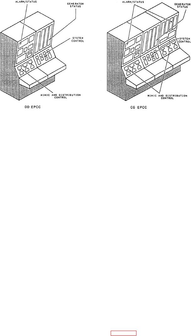
Figure 3-3.--EPCC layout.
As long as these systems are in AUTO and the
6. Distilling plant
propulsion plant is in one of the three propulsion
configurations (either secure, split plant, or full power),
7. Air-conditioning (A/C) plant
the plant mode system control is enabled. With plant
mode control enabled, the operator can perform the
8. High-pressure air system
following mode changes at the PACC:
9. Ship's service air system
1. Secure to split plant (CG-47 class ships only)
10. Chilled-water expansion tank system (CG-47
2. Split plant to full power
class only)
3. Full power to split plant
11. Combat dry-air system (CG-47 class only)
4. Full power or split plant top secure
12. AEGIS pump system (CG-47 class only)
5. Change engine
You have just read about the eight control systems
available at the PACC in DD-963, DDG-993, and CG-
Now let's shift from the plant mode control system
47 class ships. Now, let's take a look at the control
to the remaining system that can be controlled at the
systems at the EPCC for these ships.
PACC, the auxiliaries.
EPCC
Auxiliaries Systems
The electric plant control systems monitor and
There are certain engineering plant auxiliaries that
control the performance and operation of the
can be both monitored and controlled by the ECSS.
equipment associated with the ship's electrical
There are other auxiliaries that can only be monitored.
systems. The EPCC contains the controls and
The following list contains the auxiliaries that can be
indicators that are used for remote operation and
either monitored or controlled at the PACC:
monitoring of the ship's service power generation and
distribution systems. Remotely produced commands
1. Waste heat boiler (WHB) (emergency stop only)
from the EPCC operate controls to sequence the
operation of equipment or control subsystem operation.
2. Seawater service (start/stop)
In fact, the operation of the equipment associated with
the electrical distribution systems is normally
3. Freshwater service (start/stop)
controlled from the EPCC.
4. Refrigeration plant
Figure 3-3 shows a typical layout of an EPCC.
Notice how each panel is dedicated to particular types
5. Sewage and waste system 6.