
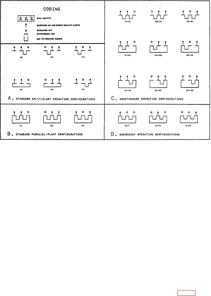
Figure 3-4.--Electric plant configurations.
EPCC by commanding either the reference
switchboard. The stop relay sends a stop signal to the
potentiometer motor (AUTO mode) or the manual
generator control panel to initiate a normal stop.
rheostat motor (MANUAL mode) in the RAISE or
LOWER direction. Just as for the generator, there
The frequency of each GTGS is controlled by an
are two modes of operation for the voltage regulator:
electronic governor. The electronic governor senses
normal and droop.
the frequency of the permanent magnet alternator
(PMA) and sends signals to a hydraulic actuator on
the gas turbine. The actuator adjusts the fuel flow in
System Configurations
the engine to maintain engine speed. The operator
can make the frequency adjustment at the EPCC by
The electrical system is designed so that two
raising or lowering a motor-driven potentiometer.
generators can supply all electrical loads. The third
There are two modes of governor operation:
GTGS can be put on standby and then automatically
NORMAL and DROOP. The NORMAL mode is
started and synchronized to the bus if one or both of
isochronous, or constant frequency. The DROOP
the on-line generators should fail. Automatic failure
mode is an alternate mode where frequency decreases
detection and recovery is available only when the
with increasing load.
EPCC is in control and in the automatic mode, and
the electric plant is in a standard parallel or standard
Generator Control
split-plant configuration.
For a GTGS, control of generator field excitation is
STANDARD
SPLIT-PLANT
accomplished by its voltage regulator. There are two
CONFIGURATION.--Standard
split-plant
modes of voltage regulator operation available at the
operation requires two generators to be on line but
EPCC: AUTO and MANUAL. In the AUTO mode, the
not paralleled. The switchboard bus of the off-line
voltage regulator regulates the generator output
generator is energized through the bus tie connection
voltage to a level set by a motor-driven reference
to one of the on-line switchboards. The remaining bus
potentiometer. In the MANUAL voltage regulator
ties are not energized. (See fig. 3-4, view A.) The
mode, excitation current from the is set by a motor-
EPCC
driven rheostat located at the switchboard. The
operator can make the voltage adjustment at the