
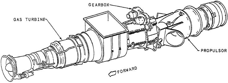
Figure 6-21.-Foilborne propulsion system.
exhaust duct through primary and secondary eductor
occurs as seawater is pumped through the water jets
nozzles, which create a flow of secondary cooling air
and expelled through a nozzle at the stem. The
through the gas turbine machinery room. Located in
reactive force resulting from the acceleration and
the aft end of the gas turbine machinery room is the
expulsion of the seawater drives the ship forward.
foilborne engine exhaust collector. When the GTE is
The main advantage of this system is its speed and
running, the exhaust works like an eductor to draw
efficiency in driving the craft forward. When
cooling air into this compartment from ventilation
foilborne, the PHM can attain speeds greater than 40
ducts through the auxiliary machinery room No. 1.
knots. A disadvantage, however, is that there is no
When the GTE is secured, fans on either side of the
provision for reversing the craft when the PHM is in
combination air inlet furnish cooling air for the
the foilborne mode.
engine and its compartment. The exhaust gases
eventually exit through the foilborne engine exhaust
The basic foilborne propulsion system consists of
stack located just aft of the superstructure.
the GTE (power plant), a power train assembly, and a
propulsor assembly. In the following sections, we will
In addition to the LM2500 GTE, the gas turbine
examine the main components of the foilborne
machinery room contains other foilborne propulsion
system, starting with its power plant, the LM2500
system equipment, including the foilborne engine
GTE.
lube oil supply and return filters, engine lube oil-to-
fuel heat exchanger, engine fuel heater, propulsor
LM2500 GTE ASSEMBLY
gearbox lube oil-to-engine fuel heat exchanger for
operating in cold areas, and propulsor gear lube oil-
The power for the foilborne system is provided by
to-engine lube oil heat exchanger for operating in hot
a General Electric LM2500 GTE located in the gas
areas.
turbine machinery room. This GTE is the same type
that is used in the twin-shaft and single-shaft ships.
Lube Oil System
The gas turbine assembly consists of a gas generator,
a power turbine, a high-speed coupling shaft, and an
The LM2500 GTE lube oil system provides two
exhaust duct. At 100 percent power, this GTE is
main functions: (1) it supplies cool oil to the gas
capable of delivering 16,767 hp to the gearbox
assembly at about 3,100 rpm.
excessive friction and heat, and (2) it supplies heat
through the oil-to-fuel heat exchanger to heat the fuel
The LM2500 GTE draws combustion air through
for the gas turbine. The lube oil is stored in a 7.2-
knit-mesh filters located on the weather deck. The
gallon oil tank located over the engine. The oil is
combustion air flows through the demister panels and
gravity-fed from the storage tank to the lube and
the air intake plenum, which interfaces with the
scavenge pump mounted on the gas turbine. The
forward end to the gas turbine machinery room. A
single-supply element of the pump forces the lube oil
barrier wall and seal prevent any air from the area
through tubes to the specific areas requiring
surrounding the engine from entering the combustion
lubrication.
air intake. The exhaust gases flow from the GTE