
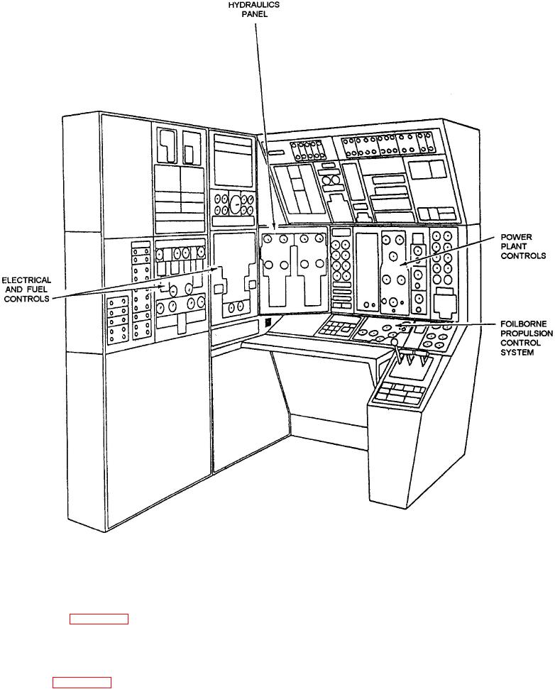
Figure 6-23.-Engineer operating station (EOS) showing panel arrangement.
position. Flow lines are shown and bilge flooding
The EOS control panel arrangement is shown in
panels and are connected through certain
on the fuel, electrical, hydraulic, seawater,
annunciators as part of the display. Alarm
freshwater, figure 6-23. The power plant
annunciators flash in conjunction with an
controls are on the main console. The electrical
audible alarm when an alarm indication is
and fuel controls are on the inboard cabinet. The
received. When the operator presses the flashing
hydraulic panel is placed diagonally at the
annunciator, the audible alarm is silenced and
corner. A more detailed view of a control panel is
the visual alarm becomes steady. Anytime the
shown in figure 6-24. Notice that the 2-inch
alarm indication becomes normal, the lamp is
meters are front mounted and clamp held. The
extinguished. Action cutout switches allow the
dial faces are white with black markings and the
operator to isolate short-circuited sensors or
dials are configured to provide a normal
actuators.
operating pointer position at the 9 o'clock