Hullborne Throttle System
The hullborne throttle system allows for control
of hullborne engine power and position of the thrust
reversers to originate either from the pilothouse or
the EOS. It also allows for the transfer of control
between these stations when the throttle controls are
placed in the idle position.
The hullborne throttle system consists of the
throttle assembly, the throttle transfer panel
assembly in the pilothouse, and the throttle transfer
module assembly in the EOS. The throttle assemblies
at each station are identical except for paint color and
the guarded ENGINE-OFF switch, which is located
only in the pilothouse unit. The throttle assemblies
operate in conjunction with the throttle panel
assemblies at each station. This feature allows the
HBCS to transfer control of the engines between the
helm station and EOS.
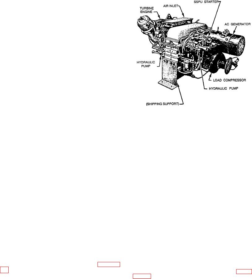
Figure 6-31.--Ship's service power unit (SSPU).
You have just read about the hullborne
propulsion system. Earlier in this chapter, you read
the panel provide a means of monitoring
about the foilborne propulsion system. In the
circuit condition.
following section, we will discuss the PHM electrical
system that allows both main propulsion systems to
Two battery chargers supply the normal dc
work.
power requirements for the craft. They also
provide the voltage required to maintain the
PHM ELECTRICAL SYSTEM
three emergency power battery sets at a
specified charge level. Battery power is used for
The
PHM
electrical
system
generates,
normal SSPU and diesel engine starts. The
distributes, and controls the craft's onboard electrical
batteries also supply normal dc power for
power. Two 450-V ac, 400-Hz, 3-phase brushless
various control circuits, indicating circuits, and
generators supply power to the craft's electrical
dc fuel pumps. The batteries are also used as an
equipment. These generators are driven by power
emergency power source to supply emergency
supplied by the ship's service power units (SSPUs).
loads after an ac voltage failure. For emergency
Switchboards and distribution panels distribute and
power, the primary source is voltage supplied
control
the
electrical
output.
from the two battery chargers paralleled with
converters, and inverters convert a portion of the
the three battery sets. A secondary emergency
generator output to lower ac and dc voltages to
power source is dc voltage supplied from two
supply the lower voltage equipment needs. Four
diesel engine alternators.
shore power receptacles, two for 400-Hz and two for
60-Hz power, are provided to receive power from
SHIP'S SERVICE POWER UNITS
shore installations or other ships upon need.
The two SSPUs that supply power to the
Basic control of the generators is at the EOS,
generators
and
other
PHM
electrical
with emergency controls and voltage/amp meters
equipment are installed in nonadjacent
provided on each switchboard. As shown in figure 6-
auxiliary engine compartments. The major
30, the EOS console contains the electrical system
components of an SSPU are shown in figure
indicator and control panel that displays the voltage,
6-31. Each SSPU includes a turbine engine
amp, frequency, and kilowatt output of each
and a mechanical gearbox. Each SSPU must
generator. This panel also provides the switches to
supply the power to drive an ac generator,
control and test the entire electrical system
two hydraulic pumps, and a load compressor,
associated with the output of each individual
all of which are mounted on the gearbox.
Each SSPU is installed by means of a 3-
voltage and current are included on this panel. Ground
point suspension and is attached to the
fault detection lights and test switches on
ship's
structure
by
means
of

