
Outside air is drawn into the compressor
through the inlet plenum into the combustor
where it is mixed with fuel. The fuel/air
mix ture is ig nited by the ig niter plug at 10
per c ent of eng ine speed. When the unit
r eac h es 95 per c en t of eng in e speed, the
ig nition sy stem is automatically de-energ ized
bec ause at this point c ombustion is self-
sustained. The hot g ases pass from the
combustion chamber into the torus assembly .
The torus assembly directs the hot g ases onto
the thr ee tur bine wheels. By impar ting ener g y
to the tur bine wheels, the hot g ases c ause
them to rotate and prov ide shaft power for
operation
of
the
compressor,
g earbox
assembly , and dr iv en equipment. The spent
g ases are ex pelled throug h the tail pipe into
the PHM ex haust duc t.
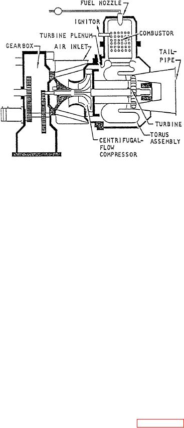
Figure 6-32.--Cutaway view showing main
components of an SSPU turbine engine.
Gearbox Assembly
The ex ternal g earbox assembly prov ides
for two of the SSPU' s mount pads and the
resilient mounts. These mounts are composed of
mou n tin g ar ea for th e SSPU' s pow er sec tion .
bonded elastomer spool pieces secured in trunnion
The internal g earbox assembly contains the
blocks.
reduction g earing that enables the power
sec tion to dr iv e the suppor ting ac c essor ies and
Normal SSPU control is maintained from the
the loading c omponents at the pr oper speed.
SSPU panel located in the EOS. The PHM electrical
When the power section is operating at 100
system allows the SSPUs to operate individually or
percent speed (41,730 rpm), the unit' s g ears
simultaneously. When both SSPUs are operating,
pr ov ide the following output speeds:
each 200-kVA, 400-Hz alternator shares the ship's
electrical load. Each SSPU is capable of supplying the
8,000 rpm
PHM's total electrical load. Reduction in electrical
load, however, is necessary for an SSPU to start the
Load compressor
8,000 rpm
LM2500 GTE.
Hydraulic pumps
3,600 rpm
Now that you have read about the general
purpose and assembly of an SSPU, let's take a closer
look at some of its main components.
Lubrication System
The
SSPU
lubrication
system
provides
SSPU Turbine Engine
lubrication for the engine and gearbox assembly, load
compressor, and generator. It is a full pressure, wet
The SSPU turbine engine is composed of four
sump system consisting of the oil pump assembly, oil
major parts: (1) a 2-stage centrifugal-flow compressor,
filter assembly, oil pressure regulator, and a check
(2) a 3-stage axial-flow turbine, (3) an inlet plenum
valve. The system is also equipped with pressure and
assembly, and (4) a combustion system. Figure 6-32 is
temperature switches and a temperature sensor for
a cutaway vie w of an SSPU turbine engine showing
readouts on the PHM indicators. The oil sump is an
the relative position of each of these components.
integral part of the SSPU assembly. The oil sump has
a capacity of 7.8 gallons and is equipped with a drain
The compressor impellers and three turbine
fitting, a dip stick, and a sight glass for monitoring
wheels are locked together by means of curvic
oil quantity. The SSPU lubrication system is
couplings. A tie bolt through the center of the wheels
serviced through a filler cap. The filler cap should
makes this assembly a single rotating unit. A floating
be removed only when the SSPU is shut down. The
ring journal bearing and seal assembly on each end of
oil
level
should
be
checked
daily.
the shaft support this rotating unit.