
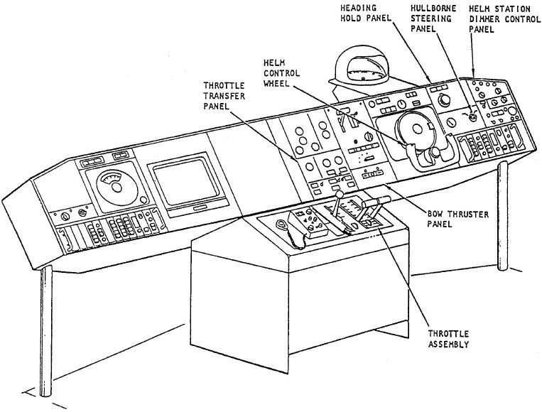
Figure 6-28.-HBCS controls at the pilothouse control console.
up and out through the inside of the compartment
MAJOR ASSEMBLIES
inlet.
Each of the two hullborne plants is made up of three
Reduction Gear
major components: (1) a diesel engine, (2) a speed reduction
gearbox, and (3) a water jet pump that acts as the propulsor
The reduction gear assembly for each hullborne
assembly. Let's take a brief look at the most important
propulsion unit is built into the diesel engine for that
design features of these components.
unit. The speed reduction gearbox drives the
propulsor assembly through an overrunning clutch
Diesel Engine
assembly.
Each hullborne propulsion unit is powered by its
Propulsor
own Mercedes-Benz Model 8V331TC81 diesel engine.
The diesel engine for each unit is located in the diesel
The hullborne propulsor assembly draws
pump and machinery room. Combustion air for the
seawater from a sea chest, accelerates the water, and
diesels and cooling air for the diesel pump and
expels it through a nozzle at the stern. The hullborne
machinery room are drawn into the space through a
propulsor inlet is a rectangular bellmouth type of
screened compartment inlet located in the forward
penetration in the hull dead rise to which the
end of the air trunk. As the diesels draw combustion
propulsor is directly attached. The propulsor and
air from this compartment, the air goes through the
inlet ducts are located in the auxiliary machinery
screens and filters and enters the diesel engines.
room.
Diesel engine exhaust gases are collected and vented