It consists of a relief valve RV-3, the bell jar itself,
and the bell jar top coupling C-2 (fig. 11-4). When
operating properly, the relief valve RV-3 has a
range of 5 to 15 psig. It is leaktight at 5 psi, and
is set to relieve at 10 psi.
Differential Pressure Gauge, DF-1
The differential pressure gauge is a bellows-
operated gauge that operates in the range of 0-100
inches H2O (inches of water). The gauge indicates
differential pressure when testing pressure closing
and opening valves.
Relief Valve, RV-11
The converter section of the test stand is
protected from excessive pressure by the RV-11
relief valve. This relief valve is set to relieve
pressure in excess of 110 psig.
Converter Supply Connection, NIP-6
The converter supply connection NIP-6
connects the converter supply coupling, through
the use of a hose, to the test stand. The flow of
oxgen shown in figure 11-5 shows that the
239.551
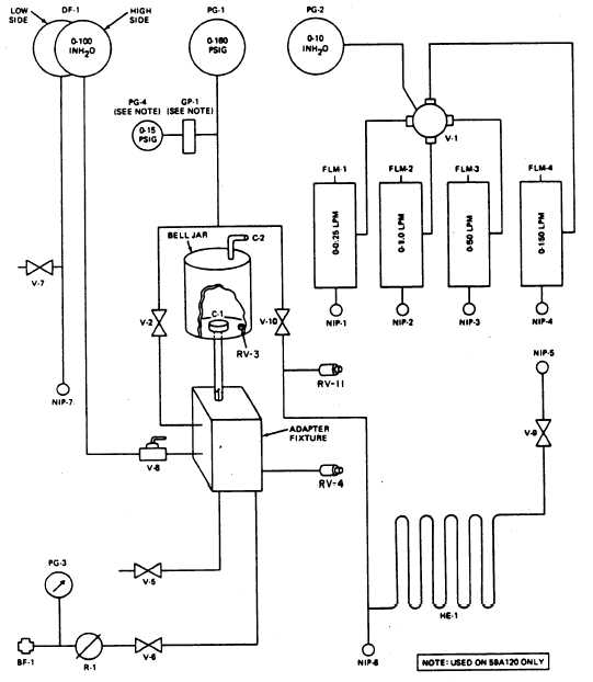
Figure 11-5.—Test stand schematic.
11-15