Installation
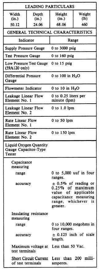
Table 11-1.—Test Stand Installation
The test stand may be installed in any
convenient location. Table 11-1 includes nominal
dimensions of the test stand. Total space
requirements can be determined by adding a
reasonable working area to the dimensions given
in the table.
NOTE: The test stand has drilled flanges
to allow stable mounting. If shock pads are
placed under the stand, they must extend
under the whole stand to give even distribu-
tion of support.
Power requirement for the test stand is 115
Vat, 400-cycle, single-phase service. The test stand
is connected to a suitable power source by the
electrical cable assembly.
A 300 to 2,000 psig oxygen source is required.
A metal strap on the left rear of the test stand
is provided for mounting and securing the oxygen
supply cylinder.
Visual Inspection
Visually inspect the test stand for the
following:
1. Dial glasses for cracks or breakage
2. All hoses for cracks or breaks
3. All pipe and hose fittings for security of
connection, worn, stripped or crossed threads
4. All tubing for severe dents or punctures
5. All valves for body cracks
6. Heat exchanger for rupture, severe dents,
or punctures
7. Gauge tester for damaged or loose parts,
and tightness of terminals and connectors
Any components found to be damaged or
defective should be repaired or replaced. Refer
to NAVAIR 17-15BC-20 for part numbers.
Test Stand Leakage Tests
Test stand leakage tests are performed by
personnel attached to the oxygen shop and
consist of setting the oxygen pressure regulator,
leak testing the accessories section, test stand
section, and Bell Jar assembly.
SETTING THE OXYGEN PRESSURE
REGUIATOR.— To set oxygen pressure regulator
11-18