torso harness suit as part of an ejection seat escape
system.
The NES-12 parachute assemblies include a
modified 28-foot diameter, flat nylon canopy with
28 gores. A ballistic spreading gun is used to
rapidly deploy the canopy. The canopy is packed
in a semirigid contoured container. These
assemblies also include the tristage external pilot
chute (EPC) and an internal pilot chute. The riser
assembly, which includes the shoulder restraint
system, is rigged to the container and is connected
to the torso harness suit with quick-release fittings.
The integrated torso harness suit combines the
aircrewman’s parachute harness and lap and
shoulder restraint straps. The harness is channeled
through the torso suit to retain it in position and
to aid in donning. When aboard the aircraft and
seated, the aircrewman connects the quick-release
fittings on the parachute riser assembly to the
quick-release fittings on the parachute integrated
torso suit. The survival kit and the lap restraint
system are also connected to the integrated torso
suit by means of quick-release fittings.
RIGGING
To obtain the NES-12 parachute, you order
each component separately. You must rig the
parts together to forma complete assembly. When
you start to work on this or any parachute, the
rigging and packing will be done under ideal
conditions in a parachute loft. When a parachute
assembly must be packed under unfavorable
conditions, provisions must be made to protect
it from possible damage and excessive humidity.
Quality assurance (QA) points are included in
rigging and packing procedures. When a step is
followed by “(QA),” it is a QA requirement. All
work STOPS until a quality assurance inspector
performs the requirements listed at the end of the
applicable procedure.
The packing of a parachute assembly must
NOT be interrupted after the packing operation
has been started. If unforeseen circumstances
cause the packing operation to be interrupted, the
parachute assembly must be completely repacked.
The rigging covered in this chapter applies to
an original issue parachute assembly.
NOTE: This rate training manual is not to
be used as a substitute for the NAVAIR
13-1-6.2 or the NAVAIR 13-600-4-6-3
manuals.
PRELIMINARY PROCEDURES
After you have laid out the parachute and
connected the connector links to the proper
tension hooks, attach the internal pilot parachute.
This is done by routing the small loop of the bridle
assembly through the loop in the pilot parachute.
Pass the free end (large loop) of the bridle
assembly through the small loop, forming a lark’s
head knot. Draw it tight. Pass one free end (large
loop) of the bridle assembly around the canopy
vent lines at the peak of the canopy. Pass the pilot
parachute through the large loop of the bridle
assembly, forming a lark’s head knot, and draw
tight. Now, attach a tension strap to the canopy
vent lines and tighten it.
At this time, you should inspect the complete
parachute assembly following the directions in
NAVAIR 13-1-6.2 and NAVAIR 13-600-4-6-3.
This inspection has been covered in chapter 1 of
this manual.
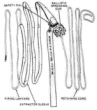
INSTALLATION OF SPREADING GUN
A ballistic spreading gun (fig. 3-3) is used
in the parachute. The procedures for inspect-
ing this device was discussed in chapter 2.
After the parachute has been inspected and
Figure 3-3.—Ballistic spreading gun assembly.
3-4