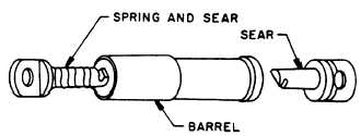
Figure 3-10.–Override disconnect.
in figure 3-10. It consists of two hooks or sears
that are kept in engagement as long as they are
inside the barrel.
As long as tension is applied to the external
pilot chute connection, the override will remain
locked. Once the internal pilot chute takes control
of the tension, the override connection will release
or unlock, allowing the external pilot chute to be
released.
To attach the external pilot parachute, proceed
as follows:
1. Insert the spring and sear (fig. 3-10) into
the wide end of the barrel assembly of the override
disconnect. The spring and sear will be connected
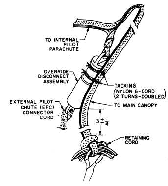
to the external pilot chute bridle, as shown in
figure 3-11. With the aid of a temporary locking
pin, push the sear into the barrel until it is
protruding from the other end.
2. Engage the sear attached to the internal
pilot chute connector cord with the sear, which
is protruding from the override disconnect, and
release the tension by removing the temporary
locking pin. This will cause the two sears to lock
within the barrel assembly of the override
disconnect. As you can see in figure 3-11, the
external and internal pilot chutes are now locked
together.
3. Tack the override disconnect to the internal
pilot parachute connector strap 3 inches (plus or
minus 1/4 inch) above the knot, securing the
connector strap to the vent lines at two places.
Use two turns of waxed nylon 6-cord (V-T0295),
doubled, for each tacking. Tie the ends with a
surgeon’s knot followed by a square knot.
SUSPENSION LINE CONTINUITY
CHECK WITH SPREADING GUN
INSTALLED
Although you have checked the continuity of
suspension lines prior to installing the spreader
gun, they must be checked again to ensure that
you haven’t gotten any lines out of sequence or
have crossed a line causing a twist. To check
suspension lines continuity, proceed as follows:
WARNING
ENSURE THE SAFETY PIN IS IN-
STALLED IN THE SPREADING GUN
(FIG. 3-12).
Figure 3-11.—Tacking override disconnects.
Figure 3-12.—Inserting safety pins.
3-7


