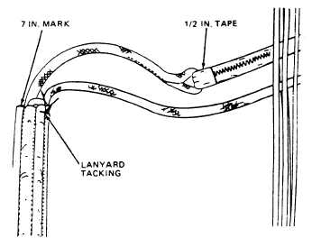
Figure 3-20.—Lanyard tacking.
Slowly remove the Type I line from the firing
lanyard bight. Rapid removal of the Type I line
from a firing lanyard bight could damage the
lanyard. Form and stow an 8-inch bight of firing
lanyard in the remaining stowage sleeve channel
in the same manner. Tack the second lanyard
bight to the stowage sleeve with one turn of waxed
size A nylon thread, single. Tie the ends with a
surgeon’s knot followed by a square knot (fig.
3-20).
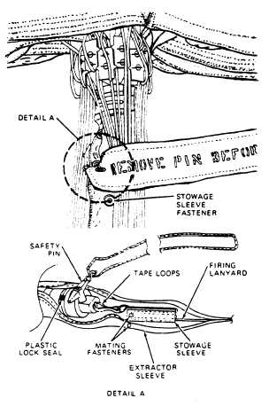
Insert the stowage sleeve into the extractor
sleeve, open end first (fig. 3-21). Engage the
fastener on the stowage sleeve to the fastener on
the extractor sleeve. Engage the extractor sleeve
fasteners on each side of the safety pin (fig. 3-22).
INSTALLATION OF AUTOMATIC
PARACHUTE RIPCORD RELEASE
ASSEMBLY
You have read about the automatic parachute
ripcord release in chapter 2 of this manual. At
this time, you will see how it is installed into a
container. Before you actually attempt to install
a release assembly, (fig. 3-23), you must first make
sure that the inspection requirements in the
NAVAIR 13-1-6.2 and the NAVAIR 13-600-4-6-3
have been complied with.
Now you are ready to proceed with the
installation.
First, rotate the risers over the suspension lines
and position the container on the packing table
so that the bottom end is towards the canopy and
3-10
Figure 3-21.—Inserting stowage sleeve.
Figure 3-22.—Engaging snaps.