The Mk 7 arresting engines have an 18:1 reeve
ratio, which means for every foot of ram travel there are
18 feet of purchase cable payout. The number of
sheaves on the crosshead determines the reeve ratio.
The types of reeves used on the Mk 7 arresting engines
are 18:1 single reeve on pendant engines, and 18:1
endless reeve on barricade engines. The endless reeve
barricade engines use only one purchase cable with the
two bitter ends terminating on the flight deck and
connected to the barricade. The single-reeved pendant
engines require two purchase cables, one reeved around
the 28-inch pitch diameter sheaves and one reeved
around the 33-inch pitch diameter sheaves of the fixed
sheave and crosshead assemblies.
FAIRLEAD SYSTEM SHEAVES
Three types of sheaves are used in Mk 7 arresting
gear. They are the horizontally mounted retractable
sheave, the vertical through-deck sheave, and the
fairlead sheave. All these sheaves are designed to
accommodate 1 7/16-inch diameter purchase cable and
are made of forged aluminum alloy.
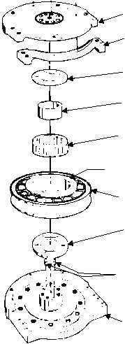
A typical sheave includes a base and cover that
retains the sheave assembly. See figure 3-27. Two
grease fittings provide access for lubricating the sheave
bearing and spacers. The sheave assembly has three
races: an inner race, a bearing race, and an outer race.
Mounted with each sheave is a two-piece concentric
spacer. The inner spacer is made of steel and is the
lubricant distributor. The outer spacer, made of
phenolic, is bonded to the sheave, provides a bearing
surface, and is a lubricant retainer for the sheave. The
horizontal and vertical sheaves are identical except for
their mounting arrangement.
The function of a retractable sheave is to provide a
means of lowering deck sheaves that would interfere
with the passage of aircraft and deck equipment when
in the raised operating position. Figure 3-28 is an
example of a retractable sheave installation.
Each retractable sheave is operated by an electric
motor unit controlled by a deckedge push-button
station. In addition, an indicator light box is installed
adjacent to the deckedge push-button station to show
the position of the sheave—a green light when the
sheave is fully raised, or a red light in all positions other
than fully raised. The retractable sheaves may also be
operated
by
means
of
handwheels
in
case
of
emergency. The handwheel is located below decks on
the operating unit. To eliminate the chance of the
retractable sheave being lowered inadvertently during
landing operations, the handwheel is removed from the
unit whenever it is not actually being used.
The retractable sheave operating unit is bolted to
the bottom of the retractable sheave assembly. It is
accessible for maintenance and manual operation from
the compartment that is directly below the retractable
sheave.
The
retractable
sheave
operating
unit
is
a
self-contained unit consisting of a high-torque electric
motor, a geared drive system, and limit switches. See
figure 3-29.
The motor is coupled to the wormshaft, which has a
worm splined to the shaft. The worm engages the worm
gear, which is free to rotate on the sleeve. There are two
lugs on the back of the worm gear that, after some free
rotation, engage two lugs on the back of the clutch
bevel gear. The free rotation is to prevent putting an
immediate load on the electric motor. The clutch bevel
gear is splined to the sleeve, so that any rotation of the
clutch bevel gear rotates the sleeve.
3-28
ABEf0327
COVER
INSERT
INNER
SPACER
INNER
RACE
OUTER SPACER
(BONDED)
SHEAVE
INNER
SPACER
GREASE
FITTINGS
BASE
BEARING
RACE
Figure 3-27.—Typical sheave assembly.


