the worm gear on the sleeve. The worm gear rotates
freely on the sleeve for part of the rotation, thus
permitting the motor to gain speed before full loading.
As the worm gear rotates, the lugs on its face engage the
lugs on the face of the clutch bevel gear. Rotation of the
clutch bevel gear, which is splined to the sleeve, rotates
the sleeve, which is directly connected to the screw of
the retractable sheave, thus raising the sheave. When
the sleeve rotates, the limit bevel gear, keyed to the
sleeve, rotates to turn the pinion of the geared limit
switch. This is the only function of the limit bevel gear.
When a predetermined point is reached by the rotor of
the geared limit switch, the RAISE circuit is broken and
the raising operation ceases. As the geared limit switch
is actuated, the green lamp (sheave UP lamp) will light
in the deckedge light box.
Energizing the motor to lower the retractable
sheave, by depressing the LOWER push button, causes
the motor and the drive system to operate in the reverse
direction. Again there is free rotation until the lugs on
the worm gear make a complete revolution before
striking the other side of the lugs on the clutch bevel
gear. The sheave lowers until it is completely seated and
opens the torque limit switch to break the motor circuit.
If an obstruction prevents the sheave from descending,
the worm, which is still rotating because of the force of
the motor, does not turn the worm gear. The worm is
driven axially along the wormshaft until the torque
limit switch is opened by the tripping plate washer. The
torque limit switch may be adjusted to permit the
sheave to seal with a predetermined force before the
circuit is interrupted. The torque spring then absorbs
the remaining inertia of the system after the circuit is
broken. During the time the sheave is lowered and
raised up until the time the RAISE geared limit switch
is tripped, the red (sheave NOT UP) lamp glows on the
deckedge light box.
For manual operation, the handwheel must be
mounted on its shaft and secured to the shaft with a
setscrew. The declutch lever must then be thrown in a
counterclockwise direction. This movement will slide
the clutch bevel gear along the splined section of the
sleeve to engage a gear on the handcrank shaft. When
the handcrank is turned, the sleeve turns, rotating the
sheave screw to raise or lower the sheave. The declutch
lever remains in the clutch position until operation
under motor power is resumed, at which time the
handwheel is disconnected automatically by the clutch
trippers. There is no danger to an operator if he or she is
turning the handwheel when the motor is started,
because the handwheel is disengaged instantly without
shock or jolt.
Thru-deck Sheave
The thru-deck sheave (fig 3-23) is mounted
vertically and it guides the purchase cable between the
sheave damper and the retractable sheave installation.
Fairlead Sheaves
Fairlead sheaves (fig. 3-23) are single sheaves that
are installed at points in the drive system where the
purchase cable require a change of direction. The
number of fairlead sheaves varies based on engine
location in relation to the location of the anchor and
sheave dampers.
Crossdeck Pendants
The polyester-core crossdeck pendant are made of
1 7/16-inch diameter, 6 × 30 flattened strand polyester
core construction with no filler wires, all wires are
considered loading bearing with a minimum breaking
strength
of
205,000
pounds.
To
differentiate
polyester-core
CDPs
from
sisal-core
CDPs
the
polyester-core terminals have a groove around the end
where the cable enters the terminal. The deck pendant
cable ends are equipped with swaged-type terminals.
These terminals are pinned to the clevis and socket
assembly at the purchase cable coupling for quick
detachment during replacement.
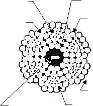
The sisal-core crossdeck pendant are made of
1 3/8-inch diameter, 6 × 30 flattened strand construc-
tion, preformed, uncoated lang lay wire rope with a
minimum breaking strength of 188,000 pounds. Each
wire rope is made up of 6 steel strands, each of which is
a bundle of 12 major and 12 intermediate wires twisted
around a triangular core of 3 to 9 wires. (See fig. 3-31.)
The strands are twisted about an oiled-hemp center
3-31
TRIANGULAR
CORE
CORE
(HEMP, FIBER)
12 MAJOR
WIRES
6 STRANDS
PER CABLE
12 INTERMEDIATE
WIRES
MANUFACTURER'S
IDENTIFICATION TAPE
INTERFACE
2
1
6
5
4
3
ABEf0331
Figure 3-31.—Cross section of preformed sisal core 6 × 30
crossdeck pendant.


