The sleeve is directly keyed to the lead screw of the
retractable sheave so that rotation of the sleeve raises or
lowers the sheave. The amount of sleeve rotation while
the sheave is rising is governed by the adjustable geared
limit switch, which opens the motor circuit when the
sheave is fully up. An adjustable torque limit switch,
actuated by the tripping plate washer, opens the motor
circuit when the sheave is fully lowered and further
provides overload protection for the unit. The worm is
normally held in position with a heavy torque spring. If
an obstruction under the sheave prevents the sheave
from lowering, the sleeve cannot turn. Then the torque
exerted by the worm exceeds the normal torque,
causing the worm to slide along the wormshaft, pushing
the tripping plate washer, and opening the torque
switch. A handwheel is provided for manual operation,
and a declutch lever is provided to change from motor
to hand operation.
It is imperative that the deckedge operator knows
whether the retractable sheave is in the UP position
during landing operations. During night operations,
visual sighting of the retractable sheave is impossible.
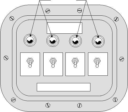
An arresting gear SHEAVE-UP and BY-PASS
switch and indicator panel (fig. 3-30) is located aft of
the arresting gear deckedge control station to indicate
the status of the retractable sheave. The panel is wired
into the clear/foul deck light and will prevent the
arresting gear officer from giving a clear deck signal if
one or more of the retractable sheaves is not in the fully
up position.
If a retractable sheave cannot be raised, the
arresting gear officer directs that the affected deck
pendant be removed from the deck. A CLEAR DECK
signal can now be activated by closing the respective
by-pass switch and thus overriding the shutdown
arresting engine. An amber warning light on the
by-pass switch and indicator panel visually indicates
the by-pass condition. In addition, a three-lamp,
deckedge indicator panel with red, amber, and green
lenses, mounted aft of the deckedge control station, will
indicate the retractable-sheave status. This panel will
illuminate red when any of the retractable sheaves are
down and green when all sheaves are up. In case one or
more arresting engine and retractable sheave is
bypassed, the deckedge indicator light will display the
green and amber lights.
SEQUENCE OF OPERATION
Energizing the motor to raise the retractable
sheave, by pressing the RAISE push button, causes the
motor to rotate a helical gear keyed to its shaft. This
transmits the motor force to another helical gear on the
wormshaft. The wormshaft turns the worm and drives
3-30
ON
OFF
BY-PASS SW
PENDANT NO.1
ON
OFF
BY-PASS SW
PENDANT NO.2
ON
OFF
BY-PASS SW
PENDANT NO.3
ON
OFF
BY-PASS SW
PENDANT NO.4
A/G SHEAVE-UP & BY-PASS
SWITCH & INDICATOR PANEL
NAEC PART NO. 617488-1
MFD BY NAEC, PHILA, PA.
CAUTION: ALL BY-PASS SWITCHES TO REMAIN IN THE
"OFF" POSITION UNLESS OTHERWISE
DIRECTED BY THE A/G OFFICER.
ABEf0330
INDICATOR LIGHTS
Figure 3-30.—Sheave-up and by-pass switch and indicator panel.


