into an extended bridle tensioner piston rod. This limit
switch is also part of the MANEUVER AFT circuit.
This circuit ensures that the tensioner piston rod is fully
aft, allowing the grab latch to remain locked to the
shuttle in an aircraft-launch-abort situation.
Internal Tensioning Components
The internal tensioning is comprised of com-
ponents that cause the retraction engine motor to slowly
rotate and consists of a pressure regulator, and a inlet
and outlet valve.
Pressure Regulator
The pressure regulator is used to reduce ac-
cumulator pressure to the pressure required to move the
grab and shuttle forward (creep rate) a distance of six
feet in 30-50 seconds.
Internal Tensioning Inlet and Outlet Valve
The internal tensioning inlet and outlet valve
controls the flow of reduced pressure hydraulic fluid to
and from the hydraulic motor and orifice bypass piping
during the tensioning phase. When actuated by the
bridle tensioner pilot valve, reduced pressure hydraulic
fluid flows through the inlet valve to the hydraulic
motor and orifice bypass piping. Hydraulic fluid from
the motor and bypass piping is routed to the gravity
tank through the outlet valve. This enables the
hydraulic motor to rotate the drum slowly so that static
friction in the retraction engine and drive system is
overcome.
Internal Tension Relief Valve
The relief valve is set to relieve at 225 psi over the
normal internal tension pressure.
HYDRAULIC SYSTEM
LEARNING OBJECTIVES: Describe the
components of the hydraulic system. Describe
the function of the hydraulic system.
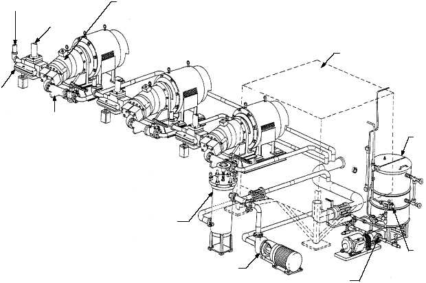
The
hydraulic
system
(fig.
4-39)
supplies
pressurized fluid to the hydraulic components of the
catapult. The system consists of a main hydraulic
accumulator, an air flask, three main hydraulic pumps,
a booster pump and filter unit, a gravity tank, a 90
gallon auxiliary tank, and a circulating pump.
4-31
TO MAIN HYDRAULIC
ACCUMULATOR
(NOT SHOWN)
DELIVERY
CONTROL
UNIT
SUCTION LINE
STRAINER
TO FLUID COOLER/
GRAVITY TANK
MAIN HYDRAULIC PUMP
GRAVITY TANK
AUXILIARY
TANK
FLUID
FILTER
CIRCULATING
PUMP
BOOSTER PUMP
BOOSTER PUMP
FILTER
ABEf0440
Figure 4-39.—Retraction engine hydraulic system.