components that cause the retraction engine motor to
slowly rotate (internal tension). The components of the
external tensioning system is comprised of a bridle
tensioner pilot valve, a pressure regulator, a tensioner
control valve, a tensioner cylinder, a relief valve, and a
full aft limit switch.
NOTE
The Mk 2 nose gear launch unit is an integral
part of the bridle tensioning system. Its
description and operation is discussed later in
this manual.
TENSIONER PILOT VALVE
The tensioner pilot valve is located on the
retraction engine manifold and is used to actuate the
bridle tensioner control valve, internal tensioning inlet,
and outlet valve.
PRESSURE REGULATOR
The pressure regulator is used to reduce ac-
cumulator pressure to the pressure required for the
proper application (4000 plus or minus 250-ft lbs.)
through the grab to the shuttle. Reduced pressure from
the regulator is directed to the bridle tensioner control
valve and to the forward end of the bridle tensioner
cylinder.
BRIDLE TENSIONER CONTROL VALVE
The
tensioner
control
valve
directs
reduced
hydraulic pressure from the pressure regulator to the aft
end of the tensioner cylinder during the bridle tension
phase. At other times the control valve provides a vent
to the gravity tank for the aft end of the tensioner
cylinder.
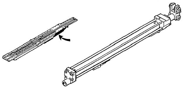
BRIDLE TENSIONER CYLINDER
The purpose of the tensioner cylinder is to exert
force on the catapult shuttle, via the shuttle grab
assembly, to tension the aircraft launching hardware
prior to launching. The bridle tensioner cylinder (fig.
4-38) is mounted directly below the nose gear launch
(NGL) track and in line with the aft trough covers. The
cylinder contains a piston with a rod extending out of
the forward end of the cylinder. The end of the rod is
fitted with a crosshead containing rollers, which
supports and aligns the piston rod within the track
formed by the two trough covers. A cam on the
crosshead is used to actuate the bridle tensioner full aft
limit switch.
RELIEF VALVE
The external tensioning relief valve is set to relieve
at 150 psi over the normally required pressure.
BRIDLE TENSIONER FULL AFT LIMIT
SWITCH
The full aft limit switch in the bridle tensioning
system is located in the aftermost trough cover, and are
actuated by a cam on the bridle tensioner piston rod
crosshead. The fully aft limit switch, when actuated,
allows completion of the RETRACT PERMISSIVE
circuit. This prevents retraction of the grab and shuttle
4-30
ABEf0439
Figure 4-38.—Tensioner cylinder assembly.