accumulator. If the system fluid use is in excess of the
primary pump output, the accumulator piston will
continue to rise causing actuation of the onstroke cam
for the other two pumps. The delivery control solenoid
of those pumps energizes and all pumps then deliver
fluid to the accumulator. As the accumulator fills, the
piston move downward reversing the movement of the
actuating arm and sequentially opening the circuits to
the delivery control solenoids of the three pumps.
VOLUME-NORMAL ACTUATOR
The volume-normal actuator is located in the top of
the
cylinder
(see
fig.
4-39).
During
launching
operations,
if
hydraulic
fluid
volume
in
the
accumulator becomes dangerously low, the concave top
surface on the accumulator piston will come in contact
with the arm on the actuator. The arm will rotate and
cause the cam to release the limit switch. The limit
switch contacts shift, lighting a malfunction light and
breaking the circuit to the cat/first ready phase of
operation.
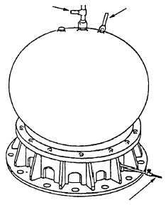
AIR FLASK
The air flask (fig. 4-41) is a 70 cubic foot container
of compressed air, which is used to maintain nearly
constant hydraulic-fluid pressure in the accumulator.
As the fluid in the accumulator is used, the air pressure
forces the piston upward, displacing the fluid. Because
of the large volume of air in the air flask, the pressure
change in the accumulator is relatively small.
MAIN HYDRAULIC PUMPS
The main hydraulic pumps (see fig. 4-39) deliver
hydraulic fluid to the main hydraulic accumulator. The
hydraulic pumps are connected in parallel. The intake
line to each pump is provided with a strainer. Each
pump discharge line is fitted with a delivery control
unit, which has a built-in relief valve. When the hydrau-
lic fluid leaves the pumps, the delivery control unit
directs it either through a fluid cooler to the gravity tank
(pump offstroke), or through the pressure line to the
main accumulator. This pressure line is equipped with
one-way check valves to prevent the backing up of fluid
from the accumulator when the pumps are offstroke.
BOOSTER PUMP AND FILTER UNIT
The booster pump and filter unit (fig. 4-42) consists
of a pump and motor assembly and a filter unit installed
between the gravity tank and the main hydraulic
pumps. The booster pump is operated anytime that a
main hydraulic pump is running. During operation the
booster pump maintains a positive head of hydraulic
pressure at the inlet to the main hydraulic pumps. The
filter unit ensures that a clean supply of hydraulic fluid
is always available. A means is provided to drain the
filter housing to facilitate changing of filter elements. A
bypass line, containing a check valve, is installed to
permit the main hydraulic pumps to take suction
directly from the gravity tank in the event of a clogged
filter unit of booster pump failure.
GRAVITY TANK
The gravity tank is the storage reservoir for catapult
hydraulic fluid. The tank is made up of internal baffles
to minimize fluid surging and foaming. The tank is
vented at the top and all low-pressure fluid return lines
lead into the top portion of the tank. The tank capacities
may vary slightly but the minimum operating tank level
with a full hydraulic system and piping is 800 gallons.
AUXILIARY TANK
The auxiliary tank (see fig. 4-39) provides a means
to return hydraulic fluid to the gravity tank or replenish
with new fluid. The tank consists of a cylindrical
shaped container with a top strainer and a lid. A line at
the bottom connects to the suction side of the
circulating pump. A flexible hose connects the top of
the tank to a flight deck fill connection. All new or
recycled hydraulic fluid must pass through the auxiliary
tank in order to get to the gravity tank.
4-33
TO MAIN HYDRAULIC
ACCUMULATOR AND
MEDIUM-PRESSURE
AIR SUPPLY VALVE
AT CHARGING PANEL
TO PRESSURE GAUGE
ON CHARGING PANEL
CONDENSATE DRAIN
VALVE
ABEf0442
Figure 4-41.—Air flask.