METERING PUMPS
The metering pumps distribute lubricating oil to the
lubricator housing located on the cylinder covers. Each
metering pump contains a piston that separates the
metering pump into two chambers, a high-pressure
hydraulic chamber and a lube oil chamber.
LUBE OIL SYSTEM OPERATIONS
With the lube air solenoid deenergized, ac-
cumulator pressure supplied to the lube control valve,
acting on the differential area on the control valve
piston will keep the control valve shifted to the air
chamber side of the control valve. This allows the
high-pressure hydraulic side of the metering pumps
(fig. 4-36) to be vented through the control valve to the
gravity tank. With the lube pump running, the metering
pumps will fill with lube oil. When all metering pumps
are full, the lube oil pump discharge pressure will
increase to the pump relief valve setting (150-165).
Pump discharge will now recirculate to the stowage
tank while maintaining relief valve setting pressure
throughout the lube oil side of the system.
When the lube air solenoid is energized, it directs
low pressure air to the air chamber of the lube control
valve, overcoming the unbalanced control valve piston.
Low pressure air shifts the control valve allowing
accumulator hydraulic pressure to be directed to the
high-pressure hydraulic side of all the metering pumps
(see fig. 4-36). The lube oil in the metering pumps is
forced out through a relief valve and to the two injectors
in each of the cylinder covers. One lube injector directs
lube oil through the open cylinder slot and the other
injector is angled to direct lube oil onto the sealing
strip.
BRIDLE TENSIONING SYSTEM
LEARNING OBJECTIVES: Describe the
components of the bridle tensioning system.
Describe the function of the bridle tensioning
system.
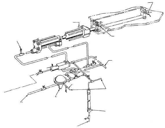
The bridle tensioning system (fig. 4-37) provides a
means of tightly connecting the aircraft to the shuttle
prior to firing the catapult. The bridle tensioning system
is comprised of components that directly apply a
forward force to the shuttle (external tension) and other
4-29
VENT VALVE
BRIDLE TENSIONER CYLINDER
BRIDLE TENSIONER FULLY-
EXTENDED LIMIT SWITCH
BRIDLE TENSIONER FULL-AFT
LIMIT SWITCH
HYDRAULIC FLUID LINE
(RETURN TO GRAVITY TANK)
RELIEF VALVE
AIR LINE
PRESSURE
REGULATOR
BRIDLE TENSIONER SURGE
ACCUMULATOR
TO TENSIONER-
ACCUMULATOR
AIR-CHARGING
VALVE AT
CHARGING PANEL
FROM MAIN
HYDRAULIC
ACCUMULATOR
FLUID SUPPLY
SHUTOFF
VALVE
ORIFICE
BRIDLE TENSIONER CONTROL
VALVE
TO TENSIONER-ACCUMULATOR-
HYDRAULIC AND DOME-AIR
PRESSURE DUPLEX GAUGE
AT CHARGING PANEL
ABEf0438
Figure 4-37.—Bridle tensioning system.