HYDRAULIC FLUID
The hydraulic fluid, MIL-H-22072, is 50 percent
water, which provides its fire resistance. The remaining
50 percent is composed of a water-soluble polymer,
which increases the viscosity of the water, the freezing
point depressant, and selected additives that impart
lubricant and corrosion protection. The red dye additive
provides good visibility for leak detection. With use,
the fluid loses water and volatile inhibitors. Water loss
is indicated by an increase in the fluid viscosity. Loss of
inhibitors is indicated by a change in the pH number of
the fluid. (External contamination will also cause a
change in pH number.) Normal values for the viscosity
and pH number of the unused fluid are as follows:
Viscosity (fluid temp. 100°F): 185 to 210 SSU
pH number: 8.8 to 9.8
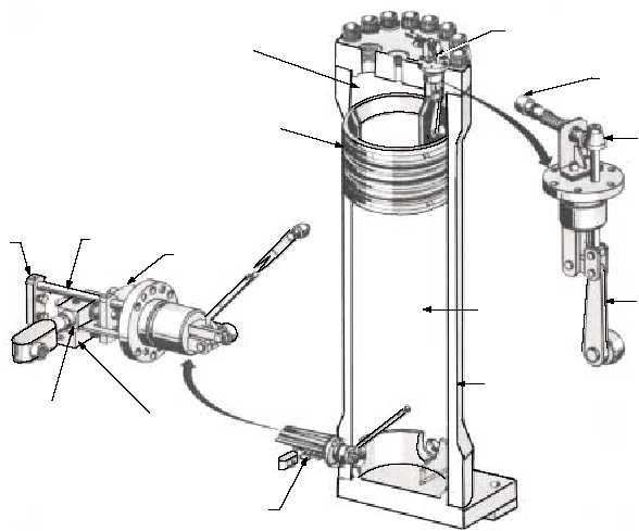
MAIN HYDRAULIC ACCUMULATOR
The main hydraulic accumulator (fig. 4-40)
consists of a vertical cylinder and a floating piston. The
piston separates the accumulator into two chambers, a
fluid chamber on top and an air chamber on the bottom.
The accumulator provides hydraulic fluid under
controlled pressure to all hydraulically operated
catapult components. The bottom chamber of the
accumulator connects by piping to the air flask and the
top chamber is connected by piping to the hydraulic
system. A stroke control actuator provides the means of
controlling main hydraulic pump delivery as required.
A volume normal actuator mounted to the top flange
provides protection from operating the catapult if the
fluid volume is low.
STROKE-CONTROL ACTUATOR
The stroke-control actuator is mounted near the
bottom of the main hydraulic accumulator cylinder.
The actuator is a lever-operated cam that operates two
limit switches. The bottom limit switch controls the
operation of the primary pump, and the top limit switch
controls the operation of the remaining two pumps.
With the accumulator full of fluid, both on stroke cams
are in the released position, deenergizing all pump
delivery control solenoids. As fluid is used, air pressure
raises the accumulator piston and the actuator rod move
upward. The on stroke cam for the primary pump
actuates first and that pump will deliver fluid to the
4-32
FLUID SIDE OF
ACCUMULATOR
VOLUME-NORMAL
ACTUATOR ASSEMBLY
PISTON ASSEMBLY
CAM
ARM
HYDRAULIC-
ACCUMULATOR
VOLUME
LIMIT SWITCH (S130)
CYLINDER
AIR SIDE OF
ACCUMULATOR
OFF-STROKE
CAM
ACTUATOR
ROD
ON-STROKE
CAM
STROKE CONTROL
LIMIT SWITCH
(S855) FOR
SECONDARY
PUMPS
STROKE CONTROL
LIMIT SWITCH
(S857) FOR
PRIMARY PUMP
STROKE CONTROL
ACTUATOR ASSEMBLY
ABEf0441
Figure 4-40.—Main hydraulic accumulator.