
using one of the following methods of inspection: For
straight hose assembly, insert a light at one end and
visually inspect from the opposite end. For elbow
fitting on both ends (practical for larger sizes only),
insert flexible inspection light into one end and visually
inspect from the opposite end using a small, angled,
dental-type mirror. Inspect for any separation of covers
or braids from inner tube, or from adjacent covers or
braids. Look for flaring or fraying of braid. Look for
blisters, bubbles, or bulging. Inspect for corrosion. A
hose that has carbon steel wire braid is subject to
corrosion, which may be detected as brownish rust
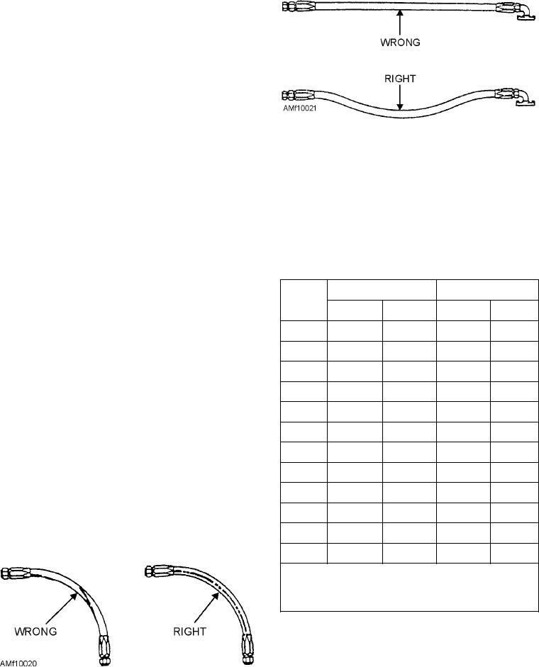
Figure 10-21.--Hose slack.
coloration penetrating the outer braid.
Inspect end fittings for proper type and size,
aligned and free of twists and kinks. Complete
corrosion and cleanliness, nicks, scratches, or other
tightening by using torque values specified in
damage to the finish that affects corrosion resistance.
applicable MIM. Table 10-8 is a guide for installation
Look for damage to threaded areas, damage to
torque of flared and flareless fittings.
cone-seat sealing surfaces, damage to flange fittings,
warping of flange, and for nicks or scratches on the
Table 10-8.--Swivel Nut Installation Torque (Inch-Pound) for
sealing surface or gasket.
Flared and Flareless Fittings
INSTALLATION PROCEDURES.--Remove
STEEL
ALUMINUM
HOSE
the protective closures from hydraulic lines, hose, or
SIZE
hose assemblies. When possible, install hose or hose
MIN
MAX
MIN
MAX
assemblies so that identification markings are visible.
2
75
85
20
30
Install hose or hose assemblies without twisting,
chafing, or overbending (fig. 10-20).
3
95
105
25
35
Observe bend radius in table 10-7. Greater
4
135
145
50
65
bend-radius is preferred where possible. Install hose or
5
170
190
70
90
hose assemblies with a slight bow or slack to
compensate for contraction pressure on the line (fig.
6
215
245
110
130
10-21).
8
430
470
230
260
When connecting hose or hose assemblies to an
10
620
680
330
360
engine or an engine-mounted accessory, provide 1 1/2
12
855
945
460
500
inches of slack or a suitable bend between the last point
of support and the engine or accessory attachment.
16
1140
1260
640
700
Fingertighten swivel connector nuts to avoid stripping
20
1520
1680
800
900
threaded areas of fittings. Before applying final torque
to end fittings, make sure hose assemblies are properly
24
1900
2100
800
900
32
2660
2940
1800
2000
NOTE: Torque values based on lubrication with fluid
MIL-H-5606 or MIL-H-83282 prior to
installation.
Hold fitting stationary with one wrench, and use
torque wrench to tighten swivel nut. When applying
final torque, hold hose manually to prevent rotation and
scoring of the fitting's sealing surface. Lockwire the
swivel nut (if applicable). Support flexible hose or hose
assemblies by routing and clamping hose or hose
Figure 10-20.--Hose twist.
10-21