
stored prior to use, it must be filled with preservative
slide. When the valve is in neutral, the slide is held in
hydraulic fluid, and then drip drained before capping.
the exact center of the sleeve by two coil springs.
These springs, working through spring guides, apply
CHECK VALVES
equal pressure to each end of the slide. Variation in
slide design will determine the valve porting.
The purpose of a check valve is to allow the fluid to
To position the slide, apply hydraulic pressure to
flow in only one direction. In some installations, such
the working surfaces at each end of it. This pressure is
as brake systems, the check valve confines fluid under
obtained from the pressure port, and is called "bleed
pressure within the desired section of the hydraulic
pressure." Body passageways direct this pressure to
system. The valve prevents the fluid from reversing its
the ends of the slide. Two solenoid assemblies are used
normal direction of flow. The valve prevents pressure
to control the flow of bleed pressure.
from escaping into adjacent sections of the system.
A solenoid is installed in each side of the valve,
Automatic Check Valves
pointing toward the center of the body. The solenoids
are tubular in shape, with coil wires wound around a
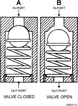
Automatic check valves contain a seat on which a
hollow center. Hydraulic fluid can enter the center
movable body (ball, cone, or poppet) seats by means of
portion, but cannot reach the coil wires. The solenoids
spring tension. (See figure 11-12.) The valve opens
are held in place by threaded caps that screw into the
when pressure in the direction of flow (indicated by an
body. The function of these solenoids is to control
arrow on the body of the valve) is strong enough to
bleed pressure.
unseat the movable body. Flow in the reverse direction,
A metal core, called a plunger, is placed in the
along with spring tension, tends to seal the movable
hollow center of the solenoids. This plunger reacts to
body against the valve seat.
the magnetic field created when the solenoid coil is
When the pressure on the downstream side of the
energized. The plunger sits above the level of the coil
valve exceeds that on the upstream side, the resultant
wires, so that when the solenoid is energized, the
unbalanced force seals the valve closed, as shown in
plunger is pulled down into the magnetic field. When
view A of figure 11-12. When the pressure is reversed,
the plunger is pulled down by the magnetic field, it
the valve is forced open against the tension of the
drives the plunger pin ahead of it. When this happens,
spring, and the fluid flows freely through the valve, as
the pin opens a passage and relieves bleed pressure
shown in view B of figure 11-12. The tension of the
from one end of the slide.
spring is relatively weak, and is intended to be barely
sufficient to support the ball in its proper position.
During all periodic inspections, selector valves are
inspected for security of installation and external
leakage. If a malfunction occurs, it must be
determined whether the cause is electrical, hydraulic,
or material failure. If the aircraft's hydraulic pressure
and electrical current are both normal, remove the
selector valve and send it to the supporting AIMD. Use
the proper 03 series maintenance publications as a
guide to clean, inspect, repair, and test the selector
valve.
Testing procedures are thoroughly outlined in the
MIMs and 03 series manuals. In general, these
procedures will consist of checking for internal and
external leakage, and on electrically controlled valves,
testing the operation of the solenoids. Before applying
pressure, make sure all air is bled out of the valve;
otherwise, a leak may exist but go undetected. As the
testing procedure begins and after the air has been bled,
the selector valve should be subjected to a low pressure
for a short period of time to allow all parts to be
Figure 11-12.--Typical check valve.
lubricated and all O-rings to seat. If the valve is to be
11-14