
applicable MIM or 03 Manual. After repair or
Malfunctioning selector valves are usually the
adjustment, all valves must be tested for proper
result of foreign particles or damaged parts. A
operation and leakage.
malfunctioning valve should be removed and checked
for free movement of the camshaft. The valve may be
Slide-Type Selector Valve
disassembled and all parts cleaned with clean
hydraulic fluid. O-rings should be replaced while the
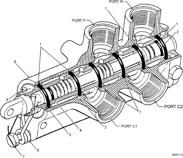
The slide-type selector valve is probably the
valve is disassembled.
most durable and trouble-free valve currently in use.
Damaged or worn O-rings may cause both external
Some manufacturers refer to this type valve as a
and internal leakage. A damaged gasket under the
piston or spool type. Figure 11-10 shows a cutaway
sealing plug or the end packing on the camshaft could
view of a typical four-port slide-type selector valve.
cause external leakage. Internal leakage could be
The main parts of the valve consist of a body, sleeve,
caused by damaged center packing on the camshaft, a
slide, detent springs, and the necessary packings and
damaged bottom gasket on the poppet seat, or damaged
gaskets.
O-ring packing on the poppet.
The valve body is cast aluminum alloy. It has four
NOTE: All selector valves that require repair or
fluid ports--pressure, return, and two cylinder ports.
A large bore has been drilled lengthwise through the
adjustment must be done in accordance with the
1.
O-ring gasket
5.
Slide
2.
O-ring packing
6.
Detent spring
3.
Sleeve
7.
Spring retaining bolt
4.
O-ring packing
8.
Body
Figure 11-10.--Slide-type selector valve.
11-11