
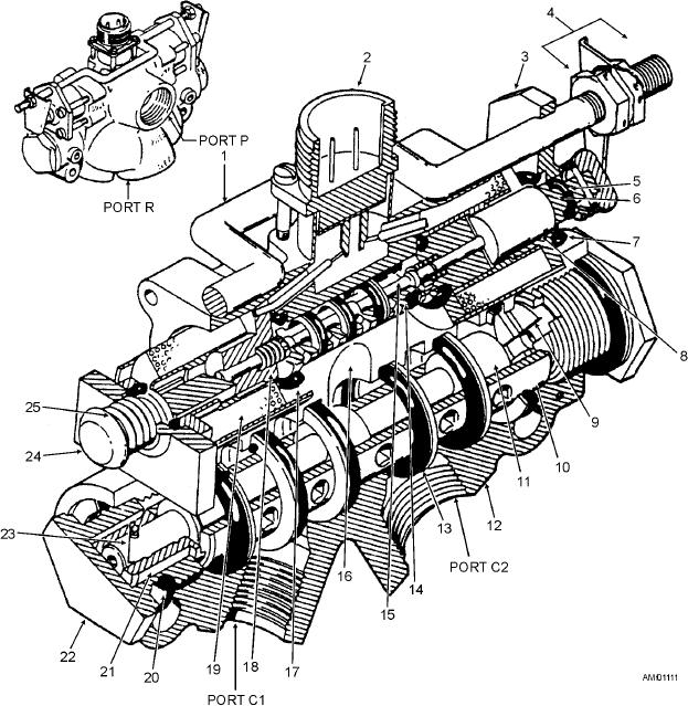
1.
Override rod
6.
Plunger shaft
11.
Selector slide
16.
O-ring and backup ring
2.
Receptacle
7.
O-ring
12.
Valve body
17.
O-ring
3.
Retainer
8.
Plunger
13.
O-ring and backup ring
18.
Pilot spring
4.
Lever assembly nut
9.
Stop
14.
Pilot sleeve
19.
Solenoid coil
5.
O-ring
10.
Selector sleeve
15.
Pilot slide
20.
O-ring and backup ring
Figure 11-11.--Solenoid-operated selector valve.
at intervals along its length. The sleeve is then inserted
A hollow steel sleeve is pressed into the body bore.
There are no flanges or grooves machined on the
through the centers of the O-rings.
sleeve, but a pattern of holes has been drilled all around
A steel slide is fitted inside the hollow sleeve. The
it. These holes are arranged in five rings, along the
slide has three lands, which form a lapped fit to the
length of the sleeve, drilled through to the hollow
inside of the sleeve. Fluid will not flow past them. By
center. When the sleeve is installed in the body, each
properly positioning the slide inside the sleeve, the
ring of holes will line up with a fluid port. The return
slide lands will connect different fluid ports by
port connects to the two outboard rings of holes. To
opening or closing the rings of holes in the sleeve. The
separate each ring of holes around the outside of the
flow of fluid to and from the actuator is directed by the
sleeve, six O-ring gaskets are installed in the body bore
11-13