
the brake should be removed and disassembled, and the
lining pucks inspected for wear.
NOTE: Linings can be measured only by
removing and disassembling the brake. If any puck has
worn to a thickness of less than one-sixteenth inch, the
entire set must be replaced. NEVER MIX NEW AND
USED LININGS.
WEAR CHECK METHOD (NO. 2).--In using
this method, have a person in the cockpit apply the
brake. With the brake applied, check the position of the
automatic adjusting pins (fig. 14-17). If any adjusting
pin recedes inside the adjusting pin nut (one-sixteenth
to three-eighth inch, the exact amount depending on
the brake model), the brake must be removed and
disassembled, and the lining thickness checked. If any
lining is worn to a thickness of one-sixteenth inch or
less, the entire set of linings must be replaced. Figure
14-17 illustrates the normal position of the automatic
adjusting pin (protruding out of the adjusting pin nut).
Emergency System Contamination Check
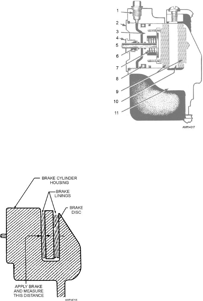
1.
Brake fluid port
7.
Piston return spring
Check the emergency system for contamination.
2.
Cylinder head
8.
O-ring packing
Remove the plug from the unused pneumatic pressure
3.
Piston
9.
Brake lining
port on the brake assembly. Position a clean, white
4.
Adjusting pin nut
10.
Brake disc
cloth adjacent to the opening, and slowly pull the
5.
Automatic adjusting pin 11.
Brake lining
emergency brake control handle. Allow airflow
6.
Adjusting pin grip
through the system for approximately 5 seconds.
Figure 14-17.--Normal position of automatic adjusting pin.
T h e r e s h o u l d b e n o ev i d e n c e o f c o m bu s t i b l e
contaminants on the cloth. If the system is
contaminated, the emergency brake pneumatic lines
from the brake control valve to the brake assembly
must be flushed with a suitable solvent. Purge for a
minimum of 15 minutes with heated nitrogen.
Bleeding Procedures
There are two general methods of bleeding brake
systems--bleeding from top downward (top-down
method) and bleeding from the bottom upward
(bottom-up method). The method used generally
depends on the type and design of the brake system to
be bled. In some instances it may depend on the
bleeding equipment available.
T O P - D OW N M E T H O D . -- I n u s i n g t h e
top-down method, the air is expelled from the system
through one of the bleeder valves provided on the brake
assembly. See figure 14-18. A bleeder hose is attached
to the bleeder valve, and the free end of the hose is
Figure 14-16.--Checking lining wear (Method No. 1).
placed in a container that has enough hydraulic fluid to
14-16