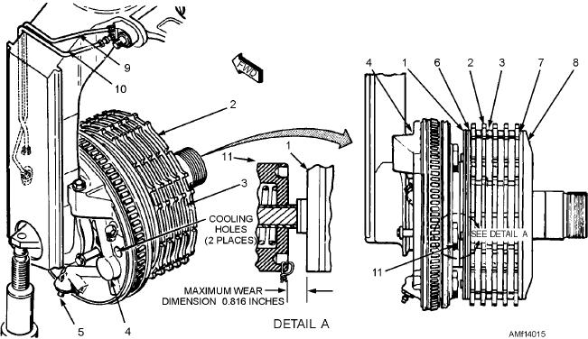
assembly (1) and the screw thread insert (11). See
Remove electrical power from the aircraft.
Depress the brake pedals several times to check
figure 14-15. Lining wear should not exceed 0.816
braking action. Place a bubble protractor on the brake
inch. Check running clearance by first applying the
pedals and adjust to zero when the brakes are in the
brake pedals until 1,200 psi is indicated on the gauges
OFF position. When the brakes are fully depressed, the
installed in the brake bleed ports. Measure the distance
protractor should indicate 30 degrees 1 degree, and
between the primary disc and the face of the screw
the hydraulic gauges on the brake assemblies should
thread insert. Release the brakes and measure the
indicate the same pressure as the external hydraulic
distance again. Subtract this dimension from that
power source.
obtained with the brakes applied to obtain the running
The external hydraulic power is shut down and
clearance. Clearance should be 0.070 to 0.119 inch.
system pressure is relieved by operating the rudder
pedals. Check brake accumulator action by fully
Brake Wear Check
depressing the brake pedals several times and checking
Lining wear may be checked by two methods.
the brake assembly action. Check the emergency brake
Before checking the brakes on any aircraft, always
system in the same manner as described for the
refer to the applicable MIM and use the method
operational checkout.
recommended by the aircraft manufacturer.
The next steps of the functional checkout require
that the wheel and tire assemblies be removed and
WEAR CHECK METHOD (NO. 1).--Have a
hydraulic power reapplied. Depress the brake pedals
person in the cockpit apply the brake, and with the
for approximately 1 minute, and check each power
brake applied, measure the distance between the face
plate for hydraulic leakage.
of the brake disc and the brake housing, as shown in
figure 14-16. If this distance has progressed to the
Check lining wear by depressing the brake pedals.
Measure the gap between the face of the primary disc
maximum specified measurement given in the MIM,
1.
Primary disc assembly
7.
Secondary disc insulation
2.
Rotors
8.
Secondary disc assembly
3.
Stators
9.
Pneumatic pressure line
4.
Power plate assembly
10.
Hydraulic pressure line
5.
Bleed valve
11.
Screw thread insert (5 each)
6.
Primary disc lining face
Figure 14-15.--Wheel brake.
14-15

