
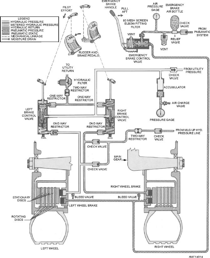
Figure 14-14.--Power/manual brake systems--schematic.
Functional Tests
When the antiskid switch is in the OFF position,
the antiskid warning light will illuminate. Move the
Prepare the aircraft for a complete functional
landing gear handle to the UP position, which will
cause the antiskid warning light to go out. The gauges
checkout by installing the landing gear down locks,
on the brake assemblies should indicate 650 to 1,000
jacking the aircraft to provide ground clearance for the
psi. Place the landing gear handle to the DOWN
landing gear, installing pressure gauges in the wheel
position to illuminate the antiskid warning light. The
brake assembly's bleed ports, and applying external
brake gauges should indicate a maximum of 75 psi, and
the wheels should be free to rotate.
electrical and hydraulic power.
14-14