
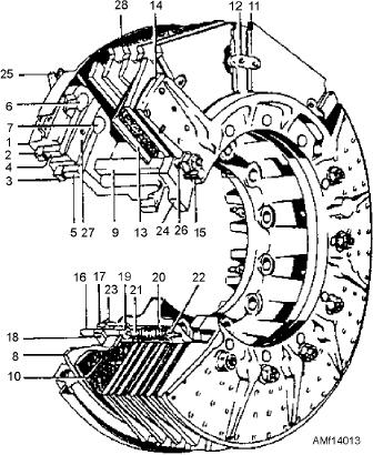
21. Adjuster sleeve
11. Rotor segment
1. Carrier assembly
22. Adjuster nut
12. Rotor link
2. Piston cup (outer)
23. Clamp holddown assembly
13. Stator plate
3. Piston cup (inner)
24. Shim
14. Backing plate
4. Piston (outer)
25. Bleeder screw
15. Torque pin
5. Piston (inner)
26.Drive sleeve bolt
16. Adjuster pin
6. Piston end (outer)
27.Dust cover (inner)
17. Adjuster clamp
7. Piston end (inner)
28.Dust cover (outer)
18. Adjuster screw
8. Pressure plate
19. Adjuster washer
9. Stator drive sleeve
20. Adjuster return spring
10. Auxiliary stator and lining assembly
Figure 14-13.--Segmented rotor brake--cutaway view.
GENERAL BRAKE SYSTEM
hydraulic power is slowly applied to the utility system.
The wheels should not rotate. By placing the landing
MAINTENANCE
g e a r h a n d l e t o t h e D OW N p o s i t i o n , i t s h o u l d
Proper functioning of the brake system is of the
illuminate the antiskid light and free the wheels to
utmost importance. Inspections must be performed at
rotate. The brake pedals should be fully depressed to
frequent intervals, and maintenance work must be
apply the brakes a minimum of three times.
performed promptly and carefully.
With external hydraulic and electrical power
Operational Checks
removed from the aircraft, operationally check the
emergency system by pulling the emergency brake
Prepare the aircraft for an operational checkout by
installing the landing gear down locks, jacking the
handle. The wheels should not rotate when the handle
aircraft to provide proper ground clearance for the
is pulled. Releasing the handle should immediately
landing gear, and applying external electrical power.
release the brakes. If any portion of the operational or
Placing the antiskid switch in the OFF position should
functional test does not meet the results specified in the
illuminate the antiskid warning light. When the
MIMs, refer to the trouble analysis sheets for the brake
landing gear handle is moved to the UP position, the
antiskid light should go out. At this point, external
system.
14-13