
Special procedures are used in the presetting
operation. Select the correct size presetting tool or a
flareless fitting body. Clamp the presetting tool or
flareless fitting body in a vise. Slide a nut and then a
sleeve onto the tube, and make sure the pilot and cutting
edge of the sleeve points toward the end of tube. Select
the lubricant from table 10-12, and lubricate fitting
threads, tool seat, and shoulder sleeve. Place the tube
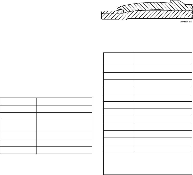
Figure 10-40.--Preset sleeve.
end firmly against the bottom of the presetting tool seat,
while slowly screwing the nut onto the tool threads with
Table 10-13.--Tube Projection from Sleeve Pilot
a wrench until the tube cannot be rotated with thumb
and fingers. At this point the cutting edge of the sleeve
TUBE SIZE
*APPROXIMATE TUBE
is gripping the tube and preventing tube rotation; the
PROJECTION-INCHES
fitting is ready for the final tightening force needed to
set the sleeve on the tube. Tighten the nut to the number
2
7/64
of turns specified in Aviation Hose and Tube Manual,
3
7/64
NAVAIR 01-1A-20.
4
7/64
5
5/32
Table 10-12.--Thread Lubricants
6
11/64
SYSTEM
LUBRICANT
8
3/16
Hydraulic
Specification MIL-H-5606
10
13/64
Fuel
Specification MIL-H-5606
12
7/32
Oil
Specification MIL-O-6032 or
16
15/64
MIL-L-23699
20
1/4
Freon
Specification MIL-L-6085A
24
1/4
Pneumatic
Specification MIL-G-4343
32
9/32
Oxygen
Specification MIL-T-27730A
*The figures vary upon change of wall thickness
for a given size. Do not use these dimensions
After presetting, unscrew the nut from the
as an inspection standard, but rather as an
presetting tool or flareless fitting body; check the sleeve
approximation of proper tube projection.
and tube (fig. 10-40). Sleeve cutting lip should be
imbedded into the tube's outside diameter between
0.003 inch and 0.008 inch, depending on size and
Proof Pressure Testing
tubing material. A lip of tube material will be raised
under the sleeve pilot. The sleeve pilot should contact
Tube assemblies that are fabricated according to
or be quite close to the outside diameter of tube. The
the instructions in Aviation Hose and Tube Manual,
tube projection from the sleeve pilot to the tube end
NAVAIR 01-1A-20, should be proof pressure tested to
should be as listed in table 10-13. The sleeve should be
twice the operating pressure of the system in which
bowed slightly. The sleeve may rotate on tube and have
they are to be installed, provided the operating pressure
a maximum lengthwise movement of 1/64 inch. The
is greater than 50 psi. Tubing, installed in systems
sealing surface of the sleeve, which contacts the
having an operating pressure of less than 50 psi must be
24-degree angle of fitting body seat, should be smooth,
proof pressure tested to a minimum of 100 psi. Vent
free from scores, and should not show lengthwise or
tubes or drain tubes do not require proof pressure
circular cracks. Crazing cracks in finish are not harmful
testing.
to safety or function of fitting. Minimum internal tube
The fluid medium for proof pressure testing of all
diameter should not be less than values shown in table
tube assemblies except oxygen systems should be a
10-14.
liquid medium such as hydraulic fluid, water, or oil.
10-34