
interact during the sequence. Figure 8-7 is a basic
extreme cases, to purge it. Refer to table 8-3. The table
contamination control sequence chart for air-
contains information to help you select an appropriate
craft system decontamination. It is a guide for
decontamination method. The table refers to chemical
decontaminating all naval aircraft and portable
analysis and particle counting, as well as to the
hydraulic test stands. The procedures outlined in the
normally performed patch testing and visual tests. You
chart reflect basic requirements of periodic maint-
may request chemical analysis and actual particle
enance, periodic aircraft rework, and maintenance
counts of fluid samples from the NADEP materials
performed as a result of actual or suspected
engineering laboratories. You may use these test results
malfunctions.
to select a decontamination method.
Q8-19.
An aircraft's hydraulic systems should be
CONTAMINATION CONTROL SEQUENCE
operated a minimum of how many com-
plete cycles while undergoing recirculation
System decontamination is one operation of a
cleaning?
contamination control sequence that includes hydraulic
fluid sampling and analysis. Decontamination is
Q8-20.
Hydraulic test stands used for system flushing
performed when the results of sampling and analysis
must be equipped with a 3-micron absolute
indicate an unacceptable contamination level. Then,
filters and have an internal reservoir that
additional testing determines when an acceptable level
holds how many gallons?
is reached.
Q8-21.
Whenever possible, purging operations
There are many operations required during the
should be accomplished at what activity?
contamination control sequence, and these operations
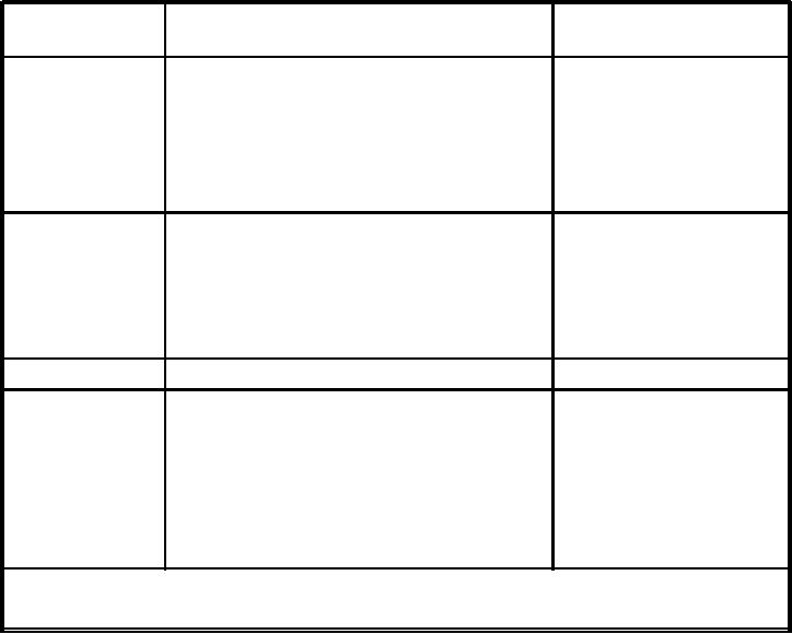
Table 8-3.--Aircraft Decontamination Requirements
TEST METHOD
ABNORMAL INDICATION
**DECONTAMINATION
METHOD REQUIRED
Visual Inspection
Free Water--standing or droplets
Flush
Dissolved Water--pinkish fluid, not clear
Flush
Gelatinous Substances
Flush
Visible Gross Particulate Matter
Flush
Oxidation--dark fluid, not clear
Flush
Patch Test
Excessive Particulate--exceeds Class 5
SE Recirculation
Water Droplets or Stains
Flush
Fibers
SE Recirculation
Gross Particulate Matter--extreme contamination
Flush
from component failure or external sources
Particle Count
Excessive Particulate Matter--exceeds Class 5
SE Recirculation
Viscosity--out of limit (*) centistokes @ 100F
Chemical Analysis
Flush
(Depot)
Flash Point--less than 180F
Flush
Water--in excess of (*) ppm
Flush
Neutralization--in excess of 0.8 mg KOH/g (acid)
Flush
Chlorinated Solvents--exceeds (*) ppm
Flush
(*) Acceptable limits to be determined by the cognizant engineering activity.
8-18