
Table 11-4.--Controls and Indicators for the Refrigerant Recovery-Recycle Units
INDEX NO.
CONTROL/INDICATOR
FUNCTION
Control Switch
Controls the electrical system.
1
Circuit Breaker
Protects the electrical system.
2
Recover Port
Connection for plant drain valve hose.
3
Recover Valve
Opens recover port.
4
Equalize Valve
Allows to equalize the high and low internal pressures for
5
ease to start up under load and draining of oil.
Low Pressure Gauge
Indicates compressor suction pressure.
6
Tank Full Light
Disconnected when used with tank full bypass jumper
7
and Navy standard refrigerant cylinders.
Hour Meter
Indicates the elapsed operating time.
8
Recycle Valve
Opens recycle port.
9
Recycle Port
Connects hose to refrigerant cylinder.
10
High Pressure Gauge
Indicates high pressure going to the refrigerant cylinder.
11
Moisture Indicator
Indicates moisture level of recycled refrigerant.
12
Oil Drain Port
Connection to attach hose for draining contaminated oil.
13
Oil Drain Selector Valve
For selection of No. 1 or No. 2 accumulator for oil
14
draining.
Recover Switch
For selection of type of recovery operation (No. 1 for
15
liquid, high oil, and acid or No. 2 for vapor and light
Tank Cable Receptacle
Jumpered with MOLEX plug (tank full bypass jumper)
16
when used with Navy standard refrigerant cylinders.
Pump Down Valve
Allows pump down of unit for refrigerant change.
17
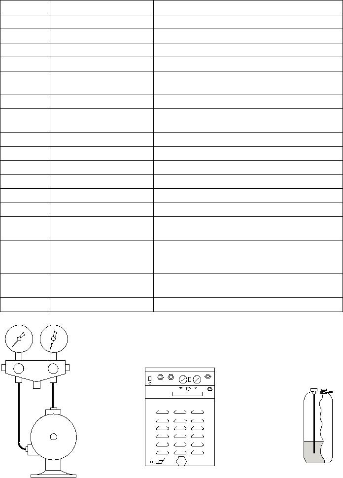
LO
HI
DUAL PORT/DUAL
ST-100A/ST-1000
ACCESS VALVE
UNIT
CYLINDER
LIQUID/GAS RECOVERY
ASf11031
Figure 11-31.--Refrigerant recovery method.
11-32