SLOTS
DRUM
CAM
ANCHOR PINS
SECONDARY
SHOE
PRIMARY
SHOE
ASf02026
PIVOT
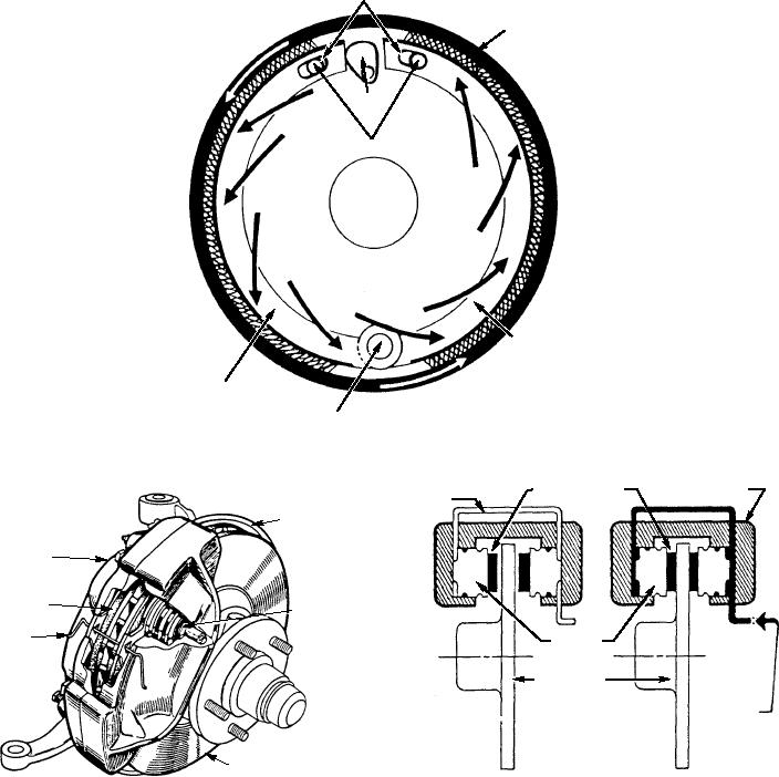
Figure 2-26.--Primary and secondary brake shoes--self-energizing action.
CONNECTING
CYLINDER
FRICTION PADS
TUBE
SPLASH
SHIELD
CALIPER
SHOE AND
LINING
PISTON
ANTI-RATTLE
SPRING
HYDRAULIC
PRESSURE
BRAKE DISK
FROM
MASTER
CYLINDER
APPLIED
RELEASED
POSITION
POSITION
ASf02027
DISK
ASf02028
Figure 2-28.--Sectional view of a disc brake in released and
applied position.
Figure 2-27.--Disc brake assembly.
indicate a faulty disc, the disc must be machined. If it is
none is available, the metal lathe in the machine shop
worn excessively, it must be replaced.
and a grinding attachment will do the job.
REPLACING DISC BRAKE LININGS.--Disc
A test should be made when shoes are replaced to
brakes have flat linings bonded to a metal plate or pad
determine if the disc has excessive runout (out of
(shoe). The pad is not rigidly mounted inside the
round) or thickness variation. Either condition will
caliper assembly, thus it is said to float. The pads are
cause erratic braking similar to that caused by a warped
held in position by retainers or internal depressions
drum on conventional brakes.
(pockets machined into the caliper).
Runout or wobble of the disc as it rotates must
Figure 2-29 shows a disc brake assembly. To
be checked with a dial indicator. Thickness variation
remove brake pads, raise the front of the vehicle and
is determined by measuring the thickness of the disc
remove the wheels. Next, remove approximately
in at least three places approximately 1 inch from the
two-thirds of the fluid from the master cylinder and
outer edge of the disc. Should either of these tests
2-20

