system should be inspected for signs of rust and
wheel cylinders are the actuators. (An actuator is a
corrosion. Maintenance includes replacement of
device that transforms fluid pressure into mechanical
force to move a mechanism.)
defective parts, servicing with required lubricants,
securing loose clamps and fittings, and straightening
A nonpetroleum-based fluid is normally used in
bent rods and shafts.
the brake systems of support equipment. The
applicable technical manual should be consulted to
Upon replacement of any component, the brakes
ensure that the correct brake fluid is used.
require adjustment to ensure both brakes are applied
equally, that they hold the unit in place when the brakes
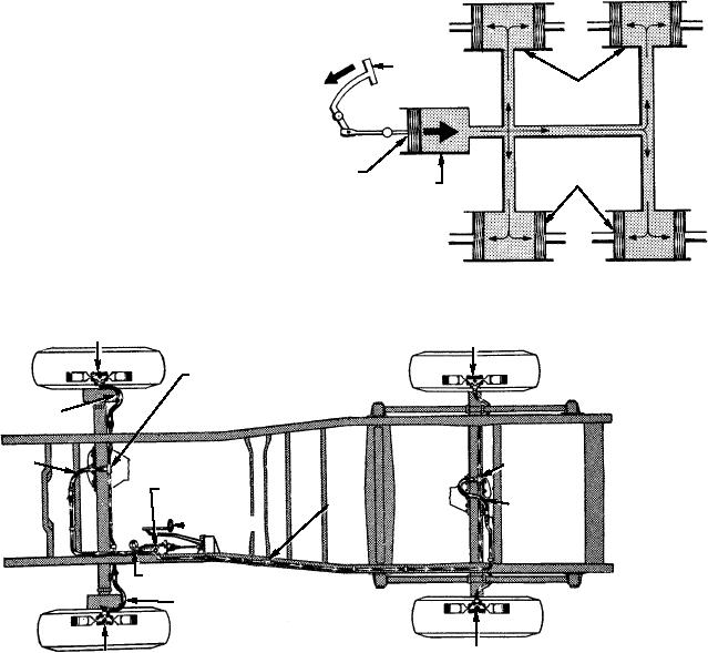
Figure 2-36 shows the operation of a hydraulic
are applied, and that they release fully when the brake
brake system. Depressing the brake pedal moves the
level is in the released position.
piston within the master cylinder, thus developing fluid
pressure. This buildup of pressure forces fluid from the
Hydraulic Brake Systems
master cylinder into the fluid lines and the wheel
cylinders.
A hydraulic brake system is primarily a liquid
connection or coupling between the brake pedal and
Like all liquids, brake fluid for all practical
the individual brake assemblies.
purposes is noncompressible. Therefore, the pressure
originated in the master cylinder is transmitted equally
A P P L I C AT I O N . -- T h e e f f e c t i v e n e s s a n d
to the wheel cylinders. This pressure, applied at the
reliability of hydraulic brake systems have been
wheel cylinders, causes the pistons to move outward.
proven through their extensive use on automobiles for
over 50 years. As a result, hydraulic systems are the
most common systems used for the operation of the
wheel brakes on powered support equipment. The
CE
hydraulic brake systems on some late model
OR
F
BRAKE PEDAL
equipment are provided with a vacuum or air booster.
WHEEL CYLINDERS
The latest hydraulic brake systems used on support
equipment tractors are true high-pressure hydraulic
systems. These systems are powered by engine-driven
MASTER
hydraulic pumps.
CYLINDER
WHEEL CYLINDER
MASTER
PISTON
CYLINDER
COMPONENTS AND OPERATION.--Figure
2-35 shows a typical arrangement of a hydraulic brake
system. The system consists of a master cylinder
connected by tubing and flexible hose to the wheel
ASf02036
cylinders. The master cylinder serves as a fluid
Figure 2-36.--Operation of hydraulic brake system.
reservoir, the system pump, and the control valve. The
FRONT WHEEL CYLINDER -- RIGHT
REAR WHEEL CYLINDER -- RIGHT
BRAKE TUBE FRONT AXLE TEE
FRONT WHEEL
BRAKE HOSE
FRONT AXLE
BRAKE HOSE
BRAKE TUBE
REAR
AXLE TEE
MASTER
CYLINDER
REAR AXLE
TUBE
BRAKE HOSE
UNION
BRAKE PEDAL
SIGNAL LAMP SWITCH
ASf02035
FRONT WHEEL
BRAKE HOSE
REAR WHEEL CYLINDER -- LEFT
FRONT WHEEL CYLINDER -- LEFT
Figure 2-35.--Typical hydraulic brake system.
2-28

