
vacuum is diminished only by operating the power
With this construction, foot pedal pressure can be
applied to the wheel cylinders for braking action
cylinder.
should vacuum or Hydrovac failure make the power
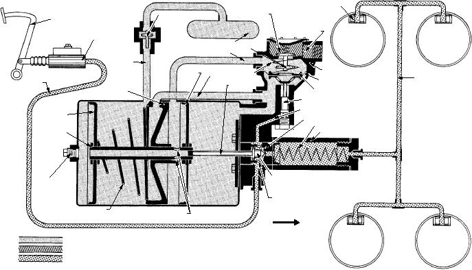
The vacuum power cylinder is divided into four
cylinder inoperative. The relay valve diaphragm has
compartments by the front and rear pistons and the
vacuum on both sides, and is held in the OFF position
center plate (fig. 2-43). The vacuum source is directly
by the valve spring. When the vacuum in the Hydrovac
connected to the compartment between the center plate
is the same as, or greater than, the source vacuum, the
and rear piston. The vacuum is connected from this
poppet valve in the vacuum check valve rests on its seat
compartment, by means of the vacuum line, to the relay
and, in the event of engine failure or rapid acceleration,
or control valve. From the control valve, the vacuum is
traps the vacuum in the Hydrovac system in readiness
connected to the front compartment by a passage in the
for brake application.
valve body.
As the foot pedal is depressed, fluid is forced from
In the released position, the control valve
the master cylinder through the open bypass (check)
diaphragm plate and vacuum valve seat is held down by
valve to the slave cylinder and on to the wheel cylinders
the valve spring. This keeps the vacuum valve open and
(fig. 2-44). The fluid is also forced through the drilled
the atmospheric valve closed. In this position, the
bypass passage to the relay valve hydraulic piston,
vacuum is connected through the vacuum valve and the
which is forced outward against the pressure of the
atmospheric control line to the compartment between
valve spring. This gradually forces the diaphragm plate
the center plate and front piston and, through the parts
and vacuum valve seat toward the brakes-applied
in the hollow piston rod, to the rear compartment.
position.
Therefore, vacuum is present in all compartments in
The movement of the diaphragm first closes the
the released position, and both pistons remain
vacuum valve against its seat, sealing off the vacuum
inoperative.
from the atmospheric control line. After the vacuum
The piston return spring holds the pistons in the
valve is seated, further motion of the diaphragm causes
OFF position. The push rod, in the released position,
the atmospheric valve to leave its seat. This permits air
maintains the bypass (check) valve off its seat,
from the air cleaner to enter the atmospheric control
permitting a direct hydraulic connection from the
line, and then to the compartment between the center
master cylinder, through the hydraulic slave cylinder,
plate and the front piston. It then flows through the
hollow piston rod to the rear compartment. With the
to the wheel cylinders.
WHEEL CYLINDER
ATMOSPHERIC
VALVE (CLOSED)
VACUUM CHECK VALVE
BRAKE PEDAL
ATMOSPHERIC FROM
MASTER
ENGINE INTAKE MANIFOLD
CYLINDER
VACUUM VALVE (OPEN)
ATMOSPHERIC CONTROL LINE
VACUUM
INLET LINE
FRONT
VALVE
RELAY VALVE
PISTON
VACUUM SPRING
LOW PRESSURE
BRAKE LINE
HYDRAULIC BRAKE
DIAPHRAGM
LINE
LINE
PUSH ROD
DIAPHRAGM PLATE AND
CENTER PLATE
VACUUM VALVE SEAT
RELAY VALVE HYDRAULIC PISTON
{DLAILVLEECYPLAINDAGETOONNAY TVIALNVE
R
D
SS
C
EC O
S
ER
REL
REAR PISTON
SLAVE CYLINDER PISTON
PISTON RETURN SPRING
PISTON ROD
HYDRAULIC SLAVE CYLINDER
PIPE
BY-PASS VALVE (OPEN POSITION)
PLUG
PISTON DRILLED HOLES
PISTON RETURN SPRING
PISTON ROD DRILLED HOLES
FRONT
VACUUM
ATMOSPHERIC PRESSURE
RESIDUAL MASTER CYLINDER HYDRAULIC PRESSURE
ASf02043
Figure 2-43.--Hydrovac operation--released position.
2-35