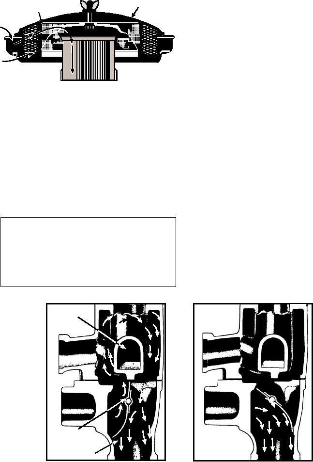
AIR INDUCTION AND EXHAUST SYSTEMS
CLEANER
C O V E R P L AT E
ELEMENT
The intake and exhaust are two of the four basic
engine strokes. The intake stroke admits an fuel-air
mixture into the cylinder, and the exhaust stroke expels
the used gases from the engine cylinder. This text
covers the intake and exhaust manifolds, the
passageways through which the mixtures are admitted,
and the gases expelled.
ASf04023
The intake manifold (fig. 4-24) is usually a
cast-iron passage through which the fuel-air mixture
passes to each cylinder. The intake manifold should be
Figure 4-23.--Dry-type air cleaner.
as short and as straight as possible to reduce chances of
condensation and to aid the flow of the mixture from
At each scheduled maintenance, remove the air
the carburetor. The manifold is mounted on the side of
cleaner and wash metallic filter elements in
the cylinder block in L-head engines, on the side of the
nonflammable cleaning solvent. Paper elements should
cylinder head in I-head engines, and between the two
be replaced at intervals recommended by the
cylinder banks in V-head engines. The intake manifold
manufacturer. Wash the other air cleaner parts. In
is fastened by cap screws or held in place by studs
wet-type cleaners, drain the old oil and add new oil. Be
extending from the cylinder block, and is secured by a
sure that the weight of the new oil conforms to the
nut and special washer on each stud. The mounting
manufacturer's specifications, and that you add it to the
flange for the carburetor is centrally located on the
level indicated on the filter body.
intake manifold so that a uniform mixture can reach the
individual cylinders. Connections between the engine
block and the manifold, and between the carburetor and
WARNING
the manifold, must be airtight. These connections are
usually sealed by thick gaskets that allow for any slight
Never wash metallic filter elements in
irregularity in the joining metal surfaces. (Leaks and
gasoline, because gasoline can be ignited by static
cracks permit air to enter the engine without passing
electricity, or even by the friction of rubbing
through the carburetor and air cleaner, resulting in a
surfaces.
lean and possibly dirty mixture.)
INTAKE
MANIFOLD
HEAT CONTROL
VALVE
EXHAUST
MANIFOLD
ASf04024
VIEW B
VIEW A
Figure 4-24.--Flow of exhaust gases around intake manifold.
4-15

