simple jack to the A/S32A-32 shipboard towing
the pump fails or a line bursts. To keep this from
tractor. Thus, the discussion, piece by piece, of a
happening, a pressure-relief valve is added to the
representative system should assist you in analyzing
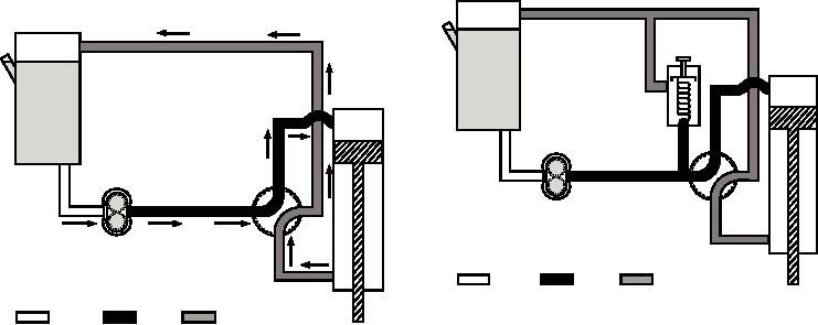
system, as shown in figure 8-44. This valve is set to
any other hydraulic system.
relieve system pressure before it becomes high enough
to rupture the system or damage the pump. The relief
REPRESENTATIVE HYDRAULIC SYSTEM
valve ball is unseated at a predetermined pressure, and
excess fluid is bypassed to the reservoir.
Basically, any hydraulic system must contain the
Although the system shown in figure 8-44 is
following elements: a pump, an actuator, a reservoir, a
workable, it is still impractical. After a few hours, an
control valve, and tubing. Figure 8-43 shows a simple
ordinary pump would probably fail because it has to
system that uses only these essentials.
maintain a constant load. (The pump is keeping the
The flow of hydraulic fluid can be easily traced
relief valve unseated except when the cylinder is being
from the reservoir through the pump to the directional
moved.) With the addition of a check valve and
valve. With the directional valve in the position
pressure regulator (fig. 8-45), the workload on the
indicated by the solid lines, the flow of fluid created by
pump is relieved, and the system is more efficient,
the pump flows through the valve to the upper end of an
safer, and more durable. (A variable displacement
actuating cylinder. Fluid pressure then forces the
pump with its own built-in pressure control serves the
piston down, and at the same time, forces out the fluid
same purpose in a system as the pressure regulator
on the lower side of the piston, up through the
valve in this system.) The pressure regulator maintains
directional valve, and back to the reservoir.
system pressure between two predetermined pressure
limits and relieves the pump when no mechanisms are
When the directional valve is rotated 90 degrees,
moving, bypassing the pump flow unrestricted back to
the fluid from the pump flows to the lower side of the
the reservoir. By adding the regulator valve to the
actuating cylinder, thus reversing the process. The
system, the relief valve becomes a safety valve, used to
movement of the piston can be stopped at any time
prevent system damage in case of regulator or variable
simply by moving the directional valve to the neutral
displacement pump control failure.
position (45-degree movement either way). In this
position, all four ports are closed and pressure is
The system shown in figure 8-45 is a practical,
trapped in both working lines.
workable system. However, more complex equipments
normally use additional components to increase
This hydraulic system would be practical if it were
efficiency, safety, and emergency or standby operation.
operated by a hand pump, such as a system common to
engine installation/removal stands and bomb trucks.
A complete hydraulic system is shown in figure
However, as the pump shown in figure 8-43 is a
8-46. In addition to the components already
power-driven, constant delivery gear pump, pressure
builds up immediately to such proportions that either
2
2
5
1
1
4
3
3
4
RETURN
PRESSURE
SUCTION
ASf08044
RETURN
PRESSURE
SUCTION
1. Actuating cylinder
4. Selector valve
2. Reservoir
5. Relief valve
ASf08043
3. Power pump
1. Actuating cylinder
3. Power pump
2. Reservoir
4. Selector valve
Figure 8-44.--Hydraulic system with a relief valve
Figure 8-43.--Simple hydraulic system.
incorporated.
8-36

