
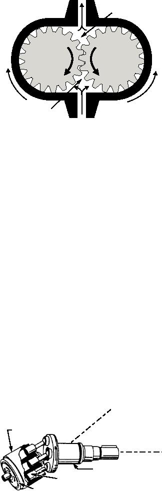
OUTLET
Q8-14. Which of the following components is
designed to dampen out system pressure
B
surges that could cause damage to a gauge?
1.
A snubber
2.
A filter
3.
A restrictor
1
2
4.
A diaphragm
Q8-15. Which of the following publications is the
authoritative reference for the calibration of
all gauges?
A
1.
NAVAIR 4790.2
ASf08041
2.
NAVAIR 17-35MTL-1
INLET
3.
NAVAIR 17-15BAD-1
Figure 8-41.--Gear-type motor.
4.
NAVAIR 17-45CAL-1
However, only one gear is connected to the output
shaft. As fluid under pressure enters chamber A, it
HYDRAULIC MOTORS
takes the path of least resistance and flows around the
inside surface of the housing, forcing the gears to rotate
A fluid power motor is a device that converts fluid
as indicated. The flow continues through the outlet port
power to rotary motion and force. Even though the
to the return. This rotary motion of the gears is
function of a motor is just the opposite of that of a
conveyed through an attached shaft to the work unit.
pump, the design and operation of fluid power motors
and pumps are very similar. In fact, some hydraulic
Although the motor illustrated in figure 8-41
pumps can be used as motors with little or no
shows operation in only one direction, a gear-type
modification. For this reason, information about
motor is capable of providing rotary motion in either
pumps given earlier in this chapter will help you
direction. For this to happen, the ports must alternate as
understand the operation of fluid power motors.
inlet and outlet. Thus, to reverse the direction of
rotation, fluid is directed through the port labeled
Motors serve many applications in fluid power
outlet into chamber B. The flow through the motor then
systems. In hydraulic power drives, pumps and motors
rotates the gears in the opposite direction of that shown
are combined with suitable lines and valves to form
in the figure, actuating the work unit accordingly.
hydraulic transmissions. The pump, commonly called
the A-end, is driven by an outside source of power,
Piston-Type Motors
such as an electric motor. The function of the pump is
to deliver fluid to the motor. The motor, called the
Like piston-type (reciprocating) pumps, the most
B-end, is actuated by the flow of fluid, and through
common design of piston-type motors is the axial. This
mechanical linkage, it conveys rotary motion and force
type of motor is most commonly used in hydraulic
to the work.
systems. (See figure 8-42.)
Fluid motors are usually classified according to the
Although some piston-type motors are
type of internal element that is directly actuated by the
controlled by directional control valves, they are
flow. The most common types of elements are gears
and pistons. Both types are adaptable for hydraulic
K
OC
systems.
L
B
ER S
ND XI
CYLINDER
LI
Gear-Type Motors
A
CY
BLOCK
OUTPUT SHAFT
The gears of a gear-type motor are of the external
AXIS
type and may be spur, helical, or herringbone design.
OUTPUT
These designs are the same as those used in gear
SHAFT
pumps.
VALVE
The operation of a gear-type motor is illustrated in
PLATE
ASf08042
Figure 8-42.--Piston-type motor.
figure 8-41. Both gears in the figure are driven.
8-34