
numbered. Note that the inner gear has one less tooth
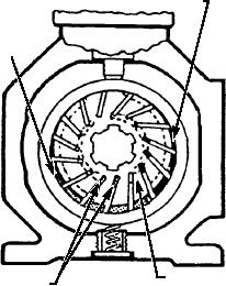
As the rotor turns, centrifugal force keeps the
than the outer gear has spaces. The tooth form of each
vanes snug against the wall of the housing. The vanes
gear is related to that of the other in such a way that
divide the area between the rotor and housing into a
each tooth of the inner gear is always in sliding contact
series of chambers. The chambers vary in size
with the surface of the outer gear. Each tooth of the
according to their respective positions around the
inner gear meshes with the outer gear at just one point
shaft. The inlet port is located in that part of the pump
during each revolution. In view A of the figure, this
where the chambers are expanding in size so that the
point is indicated by an X. In view A, tooth 1 of the
partial vacuum (low-pressure area) formed by this
inner gear is in mesh with space 1 of the outer gear. As
expansion allows liquid to flow into the pump. The
the gears continue to rotate in clockwise direction and
liquid is trapped between the vanes and is carried to the
the teeth approach point X, tooth 6 of the inner gear
outlet side of the pump. The chambers contract in size
will mesh with space 7 of the outer gear, tooth 5 with
on the outlet side, and this action forces the liquid
space 6, etc. During this revolution, tooth 1 will mesh
through the outlet port and into the system.
with space 2; and in the following revolution, tooth 1
The pump is called unbalanced because all of the
will mesh with space 3. As a result, the outer gear
pumping action takes place on one side of the shaft and
rotates at just six-sevenths the speed of the inner gear.
rotor, causing a side load. Some vane pumps are
For example, if the inner gear rotates at 1,400 rpm, the
constructed with an elliptical-shaped housing. This
outer gear rotates at 1,200 rpm.
forms two separate pumping areas on opposite sides of
At one side of the point of mesh, pockets of
the rotor, canceling out the side load. Such vane pumps
increasing size are formed as the gears rotate; while on
are called balanced. Vane pumps are used extensively
the other side, the pockets decrease in size. The pockets
in power steering units in support equipment.
on the right-hand side of the drawings increase in size
as you move down the illustration, while those on the
Reciprocating Pumps
left-hand side decrease in size. The motion of the gears
draws fluid in on one side of the pump and pushes it out
The reciprocating pump, in one form or another, is
of the other side.
perhaps the most common type of hydraulic pump
found in support equipment. This type of pump
VANE PUMPS.--Figure 8-12 shows a vane pump
depends upon the reciprocating (back-and-forth)
of the unbalanced design. The rotor is attached to the
motion of a piston inside a cylinder. The hand pump
drive shaft and is rotated by an outside power source,
and the master brake cylinder are examples of
such as an electric motor or gasoline engine. The rotor
reciprocating hydraulic pumps. There are also several
is slotted, and each slot is fitted with a rectangular
types of power-driven reciprocating pumps, driven by
vane. These vanes, to some extent, are free to move
a variety of motors.
outward in their respective slots. The rotor and vanes
are enclosed in a housing, the inner surface of which is
Reciprocating pumps are most often used for
offset with the drive axis.
applications requiring high pressure and accurate
control of the discharge volume. There are many
variations of this type of pump, which in support
DISCHARGE
equipment is normally called a piston pump. Most of
the variations, however, are based on the axial piston or
INTAKE
hand pump principle. We will look at just a few in this
chapter. (There are also radial piston pumps, but they
are seldom used in support equipment.)
HAND PUMPS.--On most hydraulic systems, a
hand pump is only a substitute for the support
equipment's main power pump in case the power fails.
However, in some support equipment, a hand pump is
the only power source.
There are two major types of hand pumps--the
single-action and the double-action. In a single-action
SLIDING
ROTATING
VANES
ASf08012
ELEMENT
pump, the fluid is drawn into the cylinder on the first
Figure 8-12.--Vane pump.
(suction) stroke and forced out of the cylinder on the
8-10