
are normally retained for use during peak load
If you follow one piston through one complete
occurrences.
revolution, you can see how the pump operates. Refer
to figure 8-15, and start with the piston at the top of its
The output of the fixed displacement pump is
cylinder. It has just completed its pressure stroke and is
determined by pump rpm and the fixed angle between
ready to begin its intake stroke. As the cylinder starts
the drive shaft and the rotating cylinder block. If the
its rotation from this point, the piston aligns
angle in a fixed displacement pump could be varied,
immediately with the intake port as it moves toward the
the piston stroke could be changed to vary the pump
bottom of the cylinder. The partial vacuum created by
output. In fact, changing the piston stroke is the method
the movement of the piston in the cylinder and the
used to vary volume on most variable displacement
gravity pressure (in some cases boost pressure) on the
pumps used in support equipment. These are called
fluid cause the space above the piston to fill with fluid.
stroke reduction pumps.
When the cylinder has gone through 180 degrees
The stroke reduction pumps shown in figures 8-16
(one-half revolution), the piston reaches the bottom of
and 8-17 are fully automatic variable displacement
the cylinder, and the cylinder is full of fluid.
pumps. The pressure compensating valves shown in
As rotation continues beyond this point, the piston
both figures use system pressure to control and vary the
now aligns with the outlet port slot. Thus, when the last
pump's piston stroke, thus changing the output.
180 degrees have been completed, the piston will have
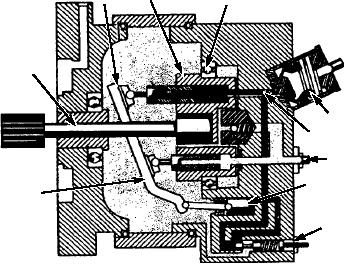
The pump piston stroke of the pump shown in
moved forward in the cylinder, and the fluid will have
figure 8-16 is determined by the angle of the cam plate.
been forced into the outlet line. At this point, the piston
The drive shaft passes through, but does not touch, the
and cylinder are again ready to start another cycle.
inclined cam plate to rotate the cylinder block and
As noted earlier, there are normally multiple
pistons. The hanger assembly in the pump shown in
pistons performing the function described above. And
figure 8-17 performs the same function as the cam
since the pump rotates rapidly, there is a constant flow
plate in the other pump.
of fluid through the outlet port. This pump normally
Va r i a b l e d i s p l a c e m e n t p u m p s m a y a l s o b e
uses case pressure and fluid flow for cooling and
configured to allow manual volume control. Manual
lubricating. Fluid seeps by the pistons in the cylinder
control can be achieved by using a hand wheel to vary
block and fills all the space inside the pump. The fluid
the piston stroke, or the pump may use manual pressure
is prevented from escaping through the drive end of the
compensating valves such as those used on many
pump by a drive shaft seal. Excessive case pressure is
hydraulic test stands.
prevented by routing the fluid back to the inlet port of
the pump through one or more relief valves. These
valves are usually set at about 15 psi. This ensures
2
3
1
circulation of fluid in the pump.
VA R I A B L E D I S P L AC E M E N T P I S T O N
PUMPS.--Variable displacement piston pumps are
4
another type of axial piston pump, and there are many
versions used in support equipment. Actually, variable
displacement pumps are used more extensively than
10
9
are fixed displacement pumps. Several different
methods are used to vary the fluid flow through the
8
pump. Some pumps vary the volume by controlling the
7
5
inlet fluid. Some vary it by changing the angle between
the pump drive shaft and the piston cylinder block.
6
Some control volume by using a system bypass within
the pump. Still others control volume by varying the
ASf08016
piston stroke.
Bearing
6. Compensator valve
1.
Cylinder
7. Stroking piston
2.
One advantage of the variable displacement pump
Piston plate
8. Inlet
3.
is that it eliminates the need for a system pressure
Drive shaft
9. Outlet
4.
regulator. A second advantage is that it provides a more
Cam plate
10. Check valve
5.
stable pressure. This reduces pressure surges and the
Figure 8-16.--Variable displacement, stroke reduction
pump with variable cam plate.
need for a system accumulator, although accumulators
8-13