
RELIEF
RELIEF VALVE OPENED
RELIEF
VALVE
BY DIFFERENTIAL
VALVE
SPRING
PRESSURE
IN
IN
OUT
OUT
FILTER
ELEMENT
ASf08021
CLOGGED FILTER
NORMAL LOW
ELEMENT
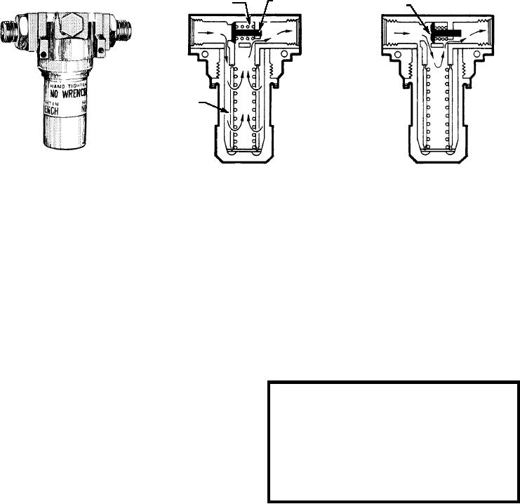
Figure 8-21.--Micronic filter.
4. The filter element shown in figure 8-19 is
the threads provides the location for packing between
removed from the case by extracting the
the filter bowl and body assembly.
retaining ring and removing the filter element.
Fluid enters the filter through the inlet port in the
NOTE: At the time of filter element replacement,
body and flows around the element inside the filter
you should never try to gauge its condition by visual
bowl. Filtering takes place as the fluid passes through
inspection alone. The naked eye cannot detect particles
the filtering element at the hollow core, leaving the dirt
smaller than 40 microns. Consequently, the element
and impurities on the outside of the filter element.
could be heavily contaminated with 10- to 20-micron
Filtered fluid then flows from the hollow core to the
particles, and the only way the condition of this
outlet port in the body and into the system.
element can be determined is by performing a back
pressure flow check on a test stand.
The bypass pressure-relief valve in the body
allows fluid to bypass the filter element and pass
directly through the outlet port in case the filter
CAUTION
element becomes clogged. In most filters of this type,
When selecting a new filter element, do not be
the relief valve is set to open if the pressure differential
guided by its appearance and physical dimensions
exceeds 50 psi. In other words, if the pressure at the
alone. Always go by the part number. Many
filter inlet port was 1,500 psi and the pressure at the
elements look identical but will disintegrate if
outlet port dropped below 1,450 psi, the relief valve
installed in the wrong type of fluid; this will cause a
would open.
good hydraulic system to become contaminated.
NOTE: Some filters of this type are not equipped
with this type of bypass pressure-relief valve.
5. Prior to installation of the replacement element,
Micronic filter elements are replaced with new
the filter head and filter case must be cleaned
filter elements at regular intervals. These intervals are
and inspected for damage. All damaged parts
specified in the applicable MIM and maintenance
must be replaced.
requirements cards (MRCs). The following procedure
6. Replace all O-ring seals.
for removing and replacing filter elements is typical of
7. Fill the filter case, if practical, one-half full of
almost all systems:
hydraulic fluid, and install the filter element in
1. Relieve system pressure.
its case and screw the case into the filter head.
2. Cut the lockwire and remove the filter case
The correct torque is usually handtight or
(bowl) from the filter head (body).
handtight plus one-eighth turn. Always check
the specific MIM.
3. Unscrew and remove the filter case, using a
slight rocking and downward pull on the case
8. Pressurize the system and inspect the filter
after the case threads are free from the filter.
assembly for leaks. If it is found satisfactory,
8-17