preventive maintenance inspections. Double-action
from the inlet chamber to the outlet chamber. Because
pumps are also used on support equipment, such as the
of the area occupied by the piston rod, the outlet
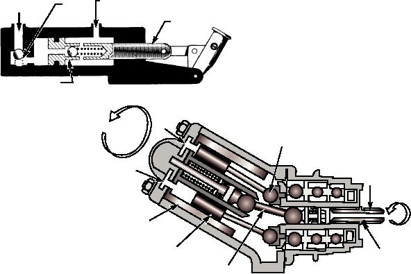
B-2 maintenance workstand. Figure 8-14 shows a
chamber cannot contain all the liquid discharged from
typical double-action hand pump.
the inlet chamber. Since the liquid will not compress,
the extra liquid is forced out of the outlet port into the
The double-action pump, shown in figure 8-14,
system, activating whatever device the pump is
consists of a cylinder, a piston with a built-in check
valve (A), a piston rod, an operating handle, and a
connected to.
check valve (B) at the inlet port. When the piston is
Maintenance of hand pumps includes frequent
moved to the left, spring tension and the force of the
pressure checks and inspections for leaks, general
liquid in the outlet chamber cause check valve A to
condition, and efficiency of operation. Operational
close. This movement causes the piston to force the
checks and removal and replacement procedures can
liquid in the outlet chamber through the outlet port and
be found in the applicable maintenance instruction
into the system. This same movement of the piston
manuals.
causes a low-pressure area in the inlet chamber.
Atmospheric pressure acting on the liquid in the
FIXED
D I S P L AC E M E N T
PISTON
reservoir transmits this pressure to the liquid at the
PUMPS.--Fixed displacement piston pumps are a
inlet port. The pressure differential acting on the ball of
type of axial piston pump. The fixed displacement
check valve B causes the spring to compress, opening
piston pump, shown in figure 8-15, produces a constant
the check valve. This allows liquid to enter the inlet
flow of fluid for any given rpm. The pistons, usually
chamber.
about nine, (always an odd number) are fastened by a
When the piston completes the stroke to the left,
universal linkage to a drive shaft. The universal link in
the inlet chamber is full of liquid. This liquid
the center drives the cylinder block, which is held at an
eliminates the low-pressure area in the inlet chamber,
angle to the drive shaft by the pump housing.
thereby allowing spring tension to close check valve B.
Everything within the pump housing rotates with the
When the piston is moved to the right, the force of
drive shaft. As the piston is rotated to the upper
the confined liquid in the inlet chamber acts on the ball
position, its movement forces fluid out of the pressure
of check valve A. This action compresses the spring
port. As the same piston moves from the upper position
and opens check valve A, allowing the liquid to flow
to the lower position, it draws in fluid through the
INLET
OUTLET
CHECK
intake port. Since each piston is always somewhere
PORT
PORT
VALVE
B
between the upper and lower positions, constant intake
PISTON
and output of fluid results. The volume output of the
pump is determined by the angle between the drive
shaft and the cylinder block, as the degree of angle
decreases or increases the piston stroke. The larger the
CHECK VALVE A
ASf08014
angle, the greater the output per revolution.
Figure 8-14.--Double-action hydraulic hand pump.
7
3
6
1
4
5
8
2
ASf08015
1. Drive shaft
3. Point of attachment
5. Piston
7. Pressure port
2. Universal link
4. Cylinder block
6. Intake port
8. Drive shaft seal
Figure 8-15.--Fixed displacement piston pump.
8-12

