
indicator is to warn the operator that the filter element
and downstream of the primary element. The second
is clogged. The equipment can then be stopped before
stage filters out any media material released by the
the bypass valve opens, thus preventing contaminated
primary element and protects the system in the event
fluid from being passed through the hydraulic system.
the primary element should fail due to excessive
differential pressure. The secondary element also
Support Equipment Hydraulic Servicing
protects the system from contamination while the
Equipment Filters
primary element is being replaced.
Other support equipment filters use only a single
To ensure delivery of contaminant-free hydraulic
stage, which consists of one large non-cleanable filter
fluid, all aircraft hydraulic servicing and test
cartridge (fig. 8-25). This configuration has been made
equipment use 3-micron (absolute) non-bypass
possible by improvements in filter elements that permit
filtration in their fluid discharge or output pressure
manufacture of a non-cleanable element capable of
lines. With many test stands, the filter used for this
withstanding 5,000 psi differential pressures and
application, in addition to having a low micron rating,
displaying negligible shedding of media material.
must be capable of withstanding high collapse
Filtration efficiency and dirt-holding capacity of the
pressures and hold large amounts of dirt. Filter
single-stage filter is comparable to that of the
assemblies and elements designed specifically for this
two-stage design, and it has the advantage of not
type of service are available from major filter
requiring second-stage element cleaning.
manufacturers and are presently being used in support
Non-cleanable, single-stage elements can be used to
equipment.
replace both the primary and secondary elements in
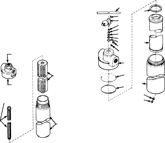
Several different types of 3-micron (absolute)
m o s t t wo - s t a g e fi l t e r a s s e m b l i e s . A p p l i c a b l e
high-pressure filters are commonly used in support
e q u i p m e n t . E a r l y m o d e l s ( fi g . 8 - 2 4 ) o f fi l t e r
assemblies used a two-stage design in which the
18
1
assembly contained both a large non-cleanable
17
primary filter cartridge and a cleanable metallic
16
s e c o n d a r y e l e m e n t . Wi t h t h i s d e s i g n , t h e
15
non-cleanable primary element provides the required
14
3-micron filtration and retains within its filter medium
13
virtually all particulate matter removed from the fluid.
12
The cleanable secondary element has a rating of 15
11
2
microns (absolute), and is physically located inside
10
9
DIFFERENTIAL
PRESSURE SWITCH
8
7
PRIMARY
FILTER
ELEMENT
3
HEAD
6
4
SECONDARY
FILTER
5
ELEMENT
ASf08025
1. Boss seal
10. Fill plug
2. Filter element
11. Preformed packing
3. Filter bowl
12. Backup ring
4. Preformed packing 13. Preformed packing
5. Drain plug
14. Sea ring
BOWL
6. Backup ring
15. Preformed packing
7. Preformed packing 16. Differential pressure switch
8. Filter head
17. Socket head cap screw
9. Preformed packing 18. Identification plate
ASf08024
Figure 8-25.--Typical high-pressure support equipment filter
Figure 8-24.--High-pressure filter.
assembly.
8-20