
6
6
5
4
5
4
3
3
7
7
2
8
2
8
1
9
9
1
10
10
11
11
ASf08028
A
B
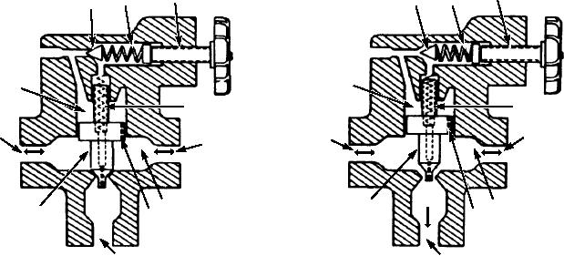
1. Piston
4. Pilot valve
7. Spring
10. Pressure port
2. Pressure port
5. Spring
8. Pressure port (inlet or outlet)
11. Return to reservoir
3. Fluid chamber
6. Adjusting screw
9. Fluid chanber
Figure 8-28.--Pilot-operated relief valve.
in both chambers 3 and 9. The tension of spring 7 then
Spring 7 will hold the piston (1) closed as long as
closes the piston (1).
the pressure in the chambers (3 and 9) remain equal.
The piston, in this condition, is referred to as being in
Relief valves of this type are used in some
hydraulic balance.
hydraulic test stands.
When an excessive pressure surge occurs, the
PRESSURE REGULATOR VALVES.--As the
pressure in chamber 3 stays basically unchanged
name implies, regulator valves are designed to regulate
because of the restriction of fluid flow of the fluid
system pressure between maximum and minimum
passage (10). The pressure surge in chamber 9
levels. These valves are often called unloading valves.
overcomes the combined pressure of chamber 3 and
They are designed to remove the system load from the
spring 7, and opens the piston (1) momentarily,
pump once the desired system pressure has been
decreasing the surge pressure by allowing fluid to flow
reached.
from chamber 9 to the return (11).
The functions performed by a regulator valve are
In a gradual pressure increase, the pressure in the
accomplished by its two operational phases--cut-in
chambers (3 and 9) remains balanced. When the
and cutout. A regulator is said to be cut-in when it is
pressure in chamber 3 equals the tension of the spring
directing fluid under pressure into a system. A
(5), the pilot valve (4) opens, thus decreasing the
regulator is cutout when it is bypassing fluid into the
pressure in chamber 3 by relieving the pressure
return line and back to the reservoir. Figure 8-29, view
through the centrally drilled passage in the piston (1).
A, shows a typical pressure regulator in the cut-in state.
The pressure in chamber 9 then exceeds the combined
In view A of figure 8-29, you can see that the pump
pressure of chamber 3 and spring 7, and thus opens the
supplies pressure to the top and bottom of the regulator
piston (1).
valve. At the top, the pressure acts on the 1/4 square
In actual operation, the piston (1) will open just
inch of the ball. On the bottom, the pressure acts on the
enough to allow excess fluid to escape. It will remain in
1 square inch of the piston. This creates a force
the open or throttled position as long as the resistance
differential between the two.
to fluid flow (causing pressure buildup) is present in
Pressure on the piston tries to lift the ball off of its
the system.
seat, but the force generated by the spring (600 lb) and
When system pressure decreases to the preset
the additional pressure exerted on the ball by the fluid
setting of the pilot valve, the tension of the spring (5)
in the upper part of the valve works to keep the ball
forces the pilot valve (4) on its seat. Because of the
seated. As long as the force differential between the
ball and the piston is less than the 600 pounds of the
passage (10) in the piston (1), fluid pressure equalizes
8-23