the actuating unit and serve alternately as pressure and
In view B, the spool is moved to the right of the
return lines. There are two main types of four-way
neutral position. In this position, one working line
control valves--the closed-center and the open-center.
(C1) is open to pressure, and the other working line
(C2) is open, through the hollow spool, to return. View
Figure 8-33 shows the operation of the valve. View
C shows the flow of fluid with the spool moved to the
A shows the valve in the neutral position. In this
left of neutral.
position, there is no flow through the valve, as the two
working ports (C1 and C2) are blocked off from the
T h e s e c o n t r o l va l ve s m a y b e d e s i g n e d a s
pressure and return ports.
individual units. However, in some systems, such as
the hydraulic systems of weapon loaders and some
View B shows the valve with the spool moved to
forklifts, two, three, or four control valves are
the left of the neutral position. In this position, one
combined into one controlling unit.
working port (C1) is open to pressure, and the other
working port (C2) is open to return. This allows the
Most directional control valves used in support
fluid to move in one direction.
equipment are operated manually, either directly or
In view C of figure 8-33, the spool is moved in the
through mechanical linkage. In some systems, these
opposite direction, to the right of the neutral position,
valves are operated electrically by solenoids.
the working port (C2) is open to pressure, and the
This is accomplished through the use of one or
working port (C1) is open to return.
more solenoids. A solenoid is a hollow, tubular-shaped
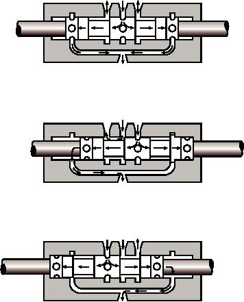
OPEN-CENTER DIRECTIONAL CONTROL
electric coil, made up of many turns of fine insulated
VALVE.--Figure 8-34 shows the operation of a
wire and possessing the same properties as an
typical open-center control valve. When this type of
electromagnet. The hollow coil imparts linear motion
valve is in the neutral position, as shown in view A,
to a movable core (or plunger) placed within the hollow
fluid flows into the valve through the pressure port
coil of the solenoid.
(P), through the hollow spool, and to the return.
To electrically operate the four-way valves shown
in figures 8-33 and 8-34, a solenoid is connected to
C1
P C2
each end of the valve. When the hollow coil of one
solenoid is energized, the plunger of the solenoid
moves and positions the sliding spool accordingly. By
energizing the solenoid on the opposite end, the sliding
spool moves in the opposite direction. Springs are
usually provided to move, and hold, the sliding spool to
TO RESERVOIR
the neutral position when neither solenoid is
A
energized. The solenoids are electrically connected to
switches that may be secured in a convenient location
C1
P
C2
for the operator. Solenoids are also used to operate
two- and three-way valves.
NOTE: In some subsystems, only one working
line is required from the control valve to the actuator. In
such systems, three-way valves are used. A three-way
TO RESERVOIR
valve contains three ports--a pressure port, a return
B
port, and one working port. Otherwise, three-way
valves operate much the same as four-way valves.
C1
P
C2
ACCUMULATORS
The purpose of an accumulator in a hydraulic
system is to store fluid under pressure. The following
are several reasons why it is useful to do this:
TO RESERVOIR
C
ASf08034
An accumulator can act as a cushion against
Figure 8-34.--Open-center directional control valve.
pressure surges in the system.
8-27

