PRESSURE
IN
RIGHT
LEFT
PORT
PORT
OUTLET
RETURN
A.
NEUTRAL
INLET
PRESSURE
IN
A.
CLOSED
SLEEVE
LEFT
RIGHT
PORT
PORT
RETURN
B.
OUTLET
FORWARD
PRESSURE
IN
INLET
RIGHT
LEFT
PORT
PORT
B.
OPEN
ASf08030
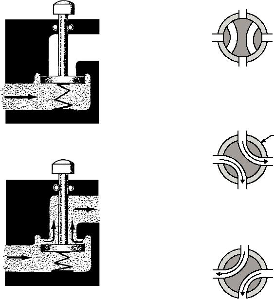
Figure 8-30.--Operation of a simple poppet valve.
RETURN
C.
of the poppet to prevent leaks past this portion of the
REVERSE
housing. In most valves, the poppet is held in the seated
ASf08031
position by a spring. Some more complex valves may
Figure 8-31.--Operation of a rotary spool valve.
have multiple poppets.
of a spool and because the valve element slides back
ROTARY SPOOLS.--A rotary spool directional
and forth to block and uncover ports in the housing.
control valve has a round core with one or more
In view B of the figure, the valve is shown in the
passages or recesses in it. (See figure 8-31.) The core is
neutral position (no fluid flow). By moving the spool
mounted within a stationary sleeve. As the core is
valve to the left position (as in view A), fluid flows
rotated within the stationary sleeve (generally by a
from the pressure line out through the right port, and
hand lever or knob), the passages or recesses connect
returns back through the left port to the return line.
or block the ports in the sleeve. The ports in the sleeve
Moving the spool to the right position (as in view C)
are connected to the appropriate pressure, working,
has a similar result; the left port becomes the pressure
and return lines of the fluid power system.
port, and the right port becomes the return port.
SLIDING SPOOLS.--A sliding spool is
Like all classes of directional control valves,
probably the most common type of valve element used
various methods are used for positioning the sliding
in directional control valves. Operation of the valve is
spool valve. Some of the more common methods are
illustrated in figure 8-32. The valve is so named
hand levers, cam angle plates, directional control arms,
and self-regulating poppet valve linkages.
because the shape of the valve element resembles that
8-25

