
cylinder of a forklift requires a full flow of fluid while
1
2
raising a load, but only a partial flow during the
lowering of the load. This is often accomplished by
using a one-way restrictor in the line. The restrictor
allows full flow during the lifting operation, but
permits only a restricted flow, thus slowing the speed
3
of actuation, during the lowering operation. Figure
8-26 shows a typical one-way restrictor.
When the fluid flows from left to right in the
restrictor, shown in figure 8-26, the pressure of the
fluid overcomes spring tension and forces the cone to
the open position. This action permits free flow
4
through large orifices in the valve. When the fluid
flows from right to left, the cone is forced closed and
the flow of fluid is restricted through the small orifice
in the cone.
Pressure Control Valves
The most common pressure control valve is the
5
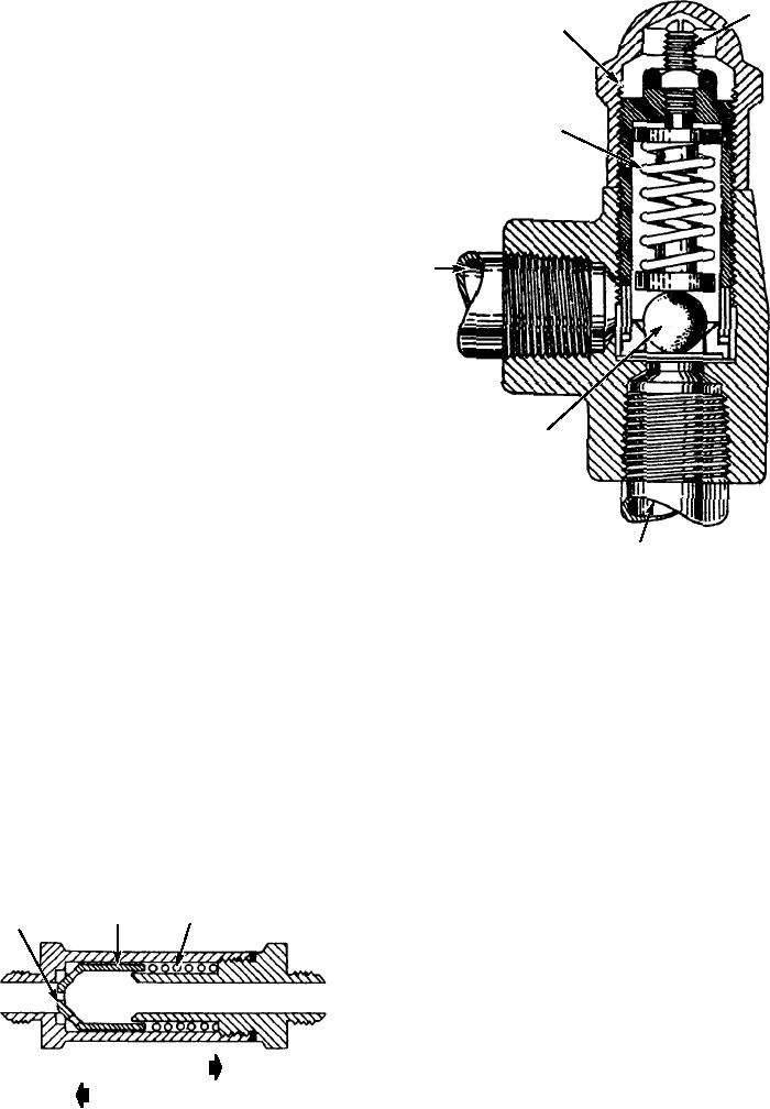
relief valve. Relief valves are pressure-limiting
devices that are used in most hydraulic systems as
safety valves. A relief valve provides protection
against overloading system components. In this way
t h ey p r eve n t d a m a g e t o t h e s y s t e m d u e t o
6
over-pressurization. Relief valves are also used to limit
ASf08027
1. Adjusting screw
4. Return port
the force that can be exerted by an actuator. One
2. Adjusting screw cap
5. Ball
example of a relief valve that was described earlier in
3. Spring
6. Pressure port
this chapter was the single-action hydraulic hand
Figure 8-27.--Relief valve.
pump, shown in figure 8-13. Many of the relief valves
found in fluid power systems operate similarly to this
reservoir. When the system pressure decreases to a safe
valve.
level, the spring setting reseats the ball.
S I M P L E R E L I E F VA LV E S . -- A s i m p l e
PILOT-OPERATED RELIEF VALVES.--A
two-port relief valve is shown in figure 8-27. An
more complex relief valve is the pilot-operated relief
adjusting screw is provided so that the valve may be
valve, shown in figure 8-28. View A shows the relief
regulated to any given pressure, allowing it to be used
valve in the closed position. View B shows the valve in
on a variety of systems. Before the system pressure can
the open position. In the closed position, fluid at
become high enough to rupture the tubing or damage
system pressure flows through the inlet port (2 or 8),
the system units, it exceeds the pressure required to
around the piston (1), and out the outlet port (2 or 8).
overcome the relief valve spring setting. This pushes
(Inlet and outlet ports may be used interchangeably
the ball off of its seat and bypasses excess fluid to the
when the valve is mounted in the pressure line, or one
SPRING
CONE
ORIFICE
port may be plugged when the valve is connected with
a "tee" fitting off the pressure line.)
By means of the passage (10) in the piston (1),
fluid also flows into chamber 3 and acts on the pilot
valve (4), which is held on its seat by spring 5. The
force of spring 5 is regulated by the adjusting screw (6)
FREE FLOW
and determines the pressure setting of the valve. Valve
RESTRICTED FLOW
ASf08026
operation will not remain steady if the pilot valve (4)
Figure 8-26.--One-way restrictor (check valve).
does not seat properly.
8-22