stem of the valve to be opened is centered under the
circular part of the keyhole slot. The three keyhole
slots are arranged in the sliding-bar to allow the
opening of only one valve at a time. To position the
sliding- bar, loosen the two locknuts and slide the bar
through the oblong slots to the desired position and
tighten the nuts.
SPRAY SHIELDS
Aluminized glass cloth spray shields are
designed to prevent JP-5 from spraying on a hot
surface or electrical equipment, or forming an
atomized mist in the event of a gasket or strainer
leak.
In main and auxiliary machinery spaces, spray
shields are installed on flanged valve (and valve man-
ifold) bonnets, and flanged joints (including gage
lines) on piping containing flammable fluid. For areas
outside main and auxiliary machinery spaces, spray
shields are installed on flammable fluid piping
flanged valve bonnets and flanged joints located in
the direct plane of an electrical switchboard,
electrical equipment enclosure, or motor.
In the event repairs are required to piping or
valve flanges that are covered with spray shields, do
NOT reuse spray shields that have fuel on them.
FILTER/SEPARATORS
There are several different types of filters in use
in the service and transfer systems in the fleet. But,
their principle of operation and hydraulic controls are
similar. The major differences are their physical
shape and flow direction.
Filters are designed to remove 98% of all solids
and 100% of all entrained water from the fuel passing
through them. This is accomplished in a two-stage
operation by two separate faltering media installed
within the filter shell. The first stage consists of a
bank of COALESCING elements, surrounded by a
hydrophobic screen, that performs the function of
removing solids and coalescing water. Coalescing
means the bringing together of fine particles of en-
trained water to form large droplets that then fall out
of the fuel by gravity. The second stage consists of a
bank of SEPARATOR elements that perform the
function of repelling the coalesced water droplets that
were too small to fall out by gravity.
The filter is equipped with a float operated
rotary control valve that will automatically drain the
accumulated water from the filter sump and shut off
the filter discharge if more water accumulates than
can be drained off automatically. This section will
describe typical filter/separators, their operation and
maintenance, and their automatic control devices.
Main Fuel (Service) Filters
The body of the main fuel filter (fig. 4-23) con-
sists of a cylindrically shaped shell with a dome-
shaped head welded on each end. The dome-shaped
heads provide a uniform flow into and out of the
filter. The interior of the filter is divided into an inlet,
fall-out, and outlet (clearwell) by tube sheets.
TUBE SHEET.— The tube sheets are circular
metal bulkheads installed within the filter shell
where the dome-shaped heads are attached to the
cylindrical shell. They are welded throughout their
circumference to form a leakproof partition between
the inlet, fallout, and outlet chambers of the filter.
The tube sheets also provide the means of installing
the filter element mounting assemblies (both
coalescer and separator). Threaded holes, one for
each assembly, are symmetrically arranged over the
tube sheets surface.
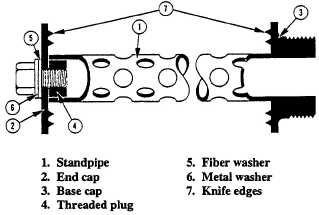
ELEMENT MOUNTING ASSEMBLY.— The
element mounting assembly (fig. 4-24) consists’ of a
perforated metal standpipe about 1 inch in diameter
and 24 inches in length, and an end cap. One end of
the standpipe is fitted with a threaded base cap to
enable screwing it into the tube sheets. The opposite
end is fitted with a threaded plug for attaching the
end cap. The end cap is a metal disk about the same
diameter as the elements.
After the filter element has been placed over the
standpipe, the end cap is secured in place by a
threaded bolt. A metal washer and fiber washer are
provided
Figure 4-24.—Element mounting assembly.
4-27