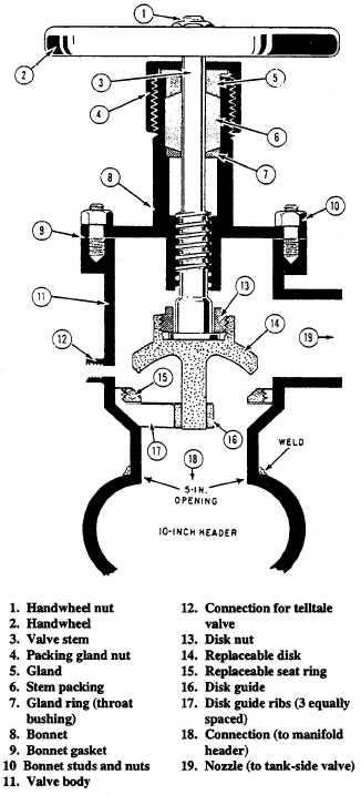
The transfer mainside valves are specially de-
signed globe valves that are welded to the top of the
manifold header (fig. 4-20). They are cylindrical in
shape (about 10 inches in diameter) and consist of a
body and bonnet. The body houses the seat ring and a
guide for the valve disk. Perfect seating of the valve
disk with the seat ring is assured by the disk guide
centered in the base of the valve body. The lower
section of the valve body is welded to the manifold
Figure 4-20.—Transfer mainside valve (cutaway).
header. A hole is machined in the back of the valve
body (above the valve seat) for attaching the nozzle.
On the front of the valve body, a hole is drilled and
tapped (also above the valve seat) for installing the
telltale valve. The bonnet, which provides a working
area for the stem, is bolted to the top of the valve
body. Leakage of JP-5 is prevented by a gasket
between the valve body and bonnet, and packing in
the bonnet packing gland around the stem.
The tankside valve is identical to the transfer
mainside valve, except there is no telltale valve con-
nection and the bottom of the valve body is fitted with
a standard pipe flange. The storage tank fill and suc-
tion tail pipe that the valve serves is bolted to this
flange.
The nozzle is a short section of pipe connecting
one transfer mainside valve to one tankside valve in
parallel so the two valves serve only one tank.
The telltale valves are small, angle type globe
valves installed on the front side of the transfer main-
side valves.
NOTE
Most ships are replacing the telltale
valve with a GAMMON sample connection.
The GAMMON sample connections are less
likely to break or leak, and require no
maintenance.
There is one telltale valve for each set of
manifold valves. These valves are installed on the
front side of the transfer mainside valves, above the
valve seat. They are used to determine the condition
of the valve seats. The telltale valves should be
opened periodically. If fuel leaks from the valve, it is
an indication either the transfer mainside or the
tankside valve is leaking. Both should be inspected as
soon as possible and the leaking valve repaired.
The manifold header drain valve is installed at
the bottom near one end of the header. It is used to
drain the header before maintenance.
A locking device is installed for each of the tank-
side valves. It is typically a bar with a rotating hook
to fit around and locked to the tankside valve handle.
It is arranged so the valve can only be locked in the
closed position. Tankside valves MUST be locked in
the closed position when the tanks are ballasted.
4-24